Biological Cells Segmentation

The task of accurate cell segmentation is essential for cellular biology and single-cell analysis, as well as for studying biological processes as a whole. In biomedical image processing, this includes reconstruction of microscopy images, foreground segmentation, cell detection, cellular compartments and organelles segmentation. Despite the tremendous progress in microscopy cell imaging and numerous segmentation methods, accurate segmentation and reliable characterization of cells remain challenging tasks that usually require problem-specific tailoring of algorithms.

The aim of our project was to develop an automatic solution for specific biological cell segmentation. Namely, it was necessary to develop a robust and precise algorithm for the automatic structural segmentation of cells containing β-catenin, a multifunctional protein that plays a crucial role in the regulation and coordination of cell-cell adhesion and gene transcription. β-catenin is expressed in different cell types and tissues and, depending on its subcellular distribution and expression levels, its imbalance often results in disease and deregulated cell growth connected to cancer and metastasis.

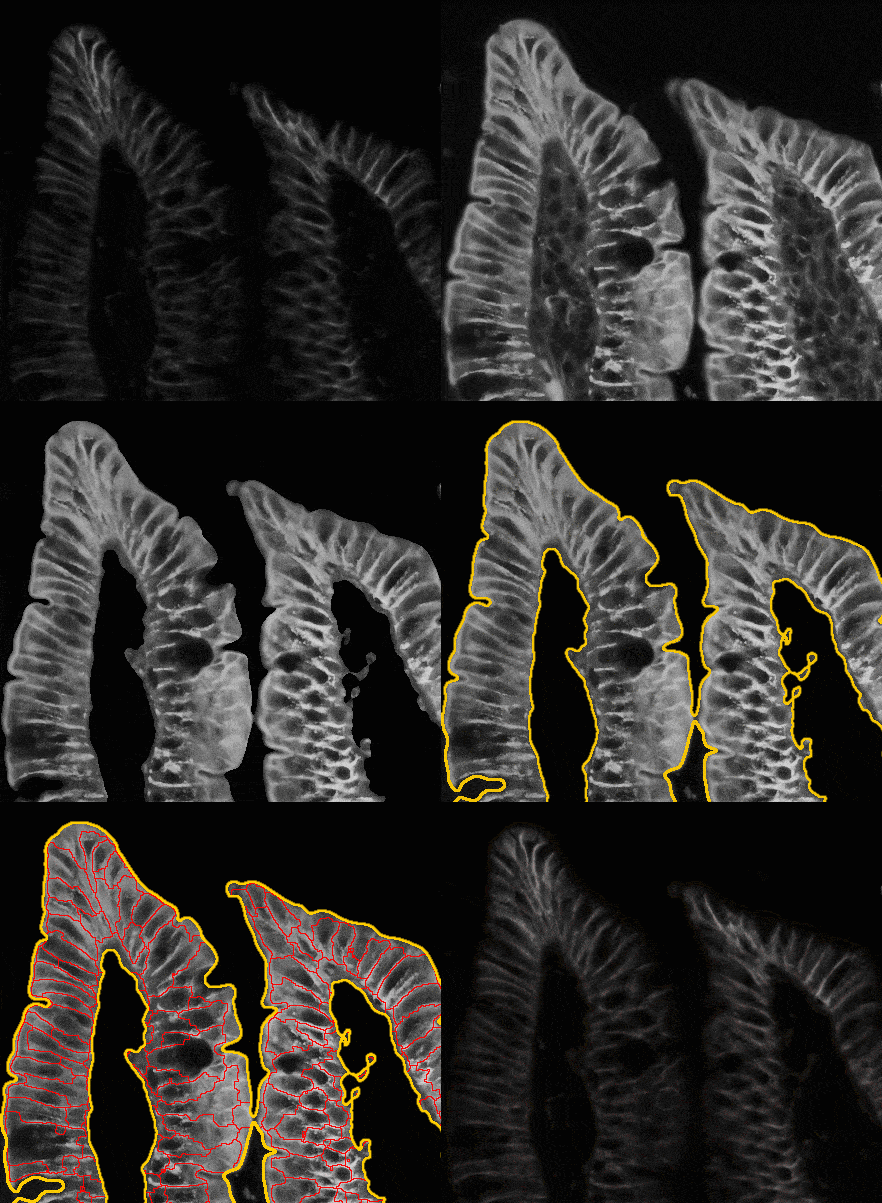
There are some issues with the segmentation of biological cells. It is often difficult to assess and determine cell boundaries visually. Some cells’ boundaries are partially invisible, some cells are overlapped. An example of a source image you can see below in Fig.1:

roi b-katenin2

Fig. 1. Source cell image

In order to develop a high-precision algorithm of cell segmentation, we applied the following scheme:

cell segmentation diagram v2

First and foremost, we improve the visual quality of the source cell image using the Adaptive histogram equalization algorithm. Also, we use some additional information to supplement some missing and invisible cell boundaries on a source image. In addition, very simple image filtration was applied to remove unnecessary cell candidates.

The main steps of image filtration are next:

  • Gaussian smoothing to remove some noise;
  • CLAHE to highlight cell boundaries;
  • A series of morphology operations, such as opening, closing, fill holes, and others;
  • Cells clustering and filtration using geometric features.

You can see noticeable changes in cell processing below.

cell segmentation diagram2

Fig. 2. Result of cells improving and filtration

To improve the segmentation algorithm and localize items more accurately, DAPI (fluorescent probe for staining of DNA) images were used.

roi dapi colored

Fig. 3. DAPI fluorescent image

Watershed segmentation was applied to the DAPI images to obtain markers (labels) for the characterization of cells with nuclear accumulation of β-catenin.

Finally, DAPI markers were used for final cell segmentation with an improved watershed algorithm.

Below you can see a simple animated demo illustrating how biological cell segmentation works.

Cell segm animation

Fig. 4. Сell segmentation demo

In conclusion, being an important technique for studying biological processes, microscopy image processing remains a bottleneck in the analysis of living cells, as it implies the subjective and time-consuming intervention of human experts. Meanwhile, computer vision approaches for segmenting and analyzing the cells can address some of these challenges, thus, contributing to gain a more accurate, high-throughput, and almost autonomous view of cellular structure and functions. 

The proposed algorithm is able to identify and segment the structure of cells using AHE image reconstruction, image filtration, data augmentation, and improved watershed segmentation. Such a fusion of processing from different input images allows retrieving the structure of the required cells automatically.

Indoor Navigation System & Technologies: Comprehensive Guide

Indoor Navigation Technologies: A Comprehensive Tech & Business Guide

The development of indoor navigation systems and algorithms has become a popular trend in the IT industry in recent years. Some modern buildings, such as airports, shopping malls, and warehouses, have become so large that they require navigation tools for the customers. 

Not surprisingly, according to Business Research Insights, the market size of indoor localization and positioning systems is expected to reach $32.31 billion by 2033, with a compound annual growth rate (CAGR) of 24.5%.

Closed environment conditions prevent the use of standard satellite-based navigation systems, such as GPS or GLONASS, prompting the emergence of alternative information sources for user localization.

The concept of tracking moving objects within a confined space is not entirely new. Modern indoor navigation systems (INS) can employ various physical principles and offer location accuracy ranging from dozens of meters to centimeters. Their typical operation area or footprint, complexity, and cost may differ tens of times. 

Besides the location, indoor navigation systems can provide other related services, such as optimal routing, tracking of the most popular places people visit, and sending notifications when the user reaches a point of interest. 

In this comprehensive guide, we’ll cover indoor navigation technology from tech and business aspects, namely:

  • Fundamental approaches used in indoor positioning and navigation.
  • Top 7 types of indoor positioning systems: LTE-Direct, Wi-Fi Access Points, RFID, Geomagnetic positioning, UWB, Ultrasonic, and Beacons.
  • Pros & cons that each indoor navigation system provides.
  • Benefits and applications of indoor navigation service across various industries.
  • Challenges and emerging trends in indoor navigation implementation.
  • It-Jim’s expertise in developing indoor navigation services.

Let’s start by examining the standard approaches of indoor navigation technologies.

Approaches to the Indoor Navigation System

Let us first provide an overview of the approaches used in indoor positioning and navigation, highlighting their pros and cons, before proceeding to compare them.

All known methods of indoor navigation technology may be put into two baskets:

1) Measuring the distances to some reference points.

2) Identifying some unique tags or fingerprints.

It could be one parameter (for example, serial ID) or a combination of some parameters (for example, a matrix of reference signal measurements).

Some indoor navigation systems track the distances between the target (the user) and various reference points (beacons).

This is known as trilateration, and its more common case – multilateration [2]. Other indoor navigation systems identify some unique fingerprints to directly determine the user’s position [3], as shown in Figure 2 below.

Figure 2. Distance-based and Fingerprint-based types of indoor positioning systems

Figure 2: Distance-based and Fingerprint-based types of INS

Benefits of Implementing an Indoor Navigation System

The benefits of indoor navigation services go far beyond simply guiding someone from point A to point B. Let’s review some of these advantages.

1. Improved User Experience

At its core, any indoor navigation system helps move around unfamiliar places and huge buildings. 

For example, a patient can use a smartphone to find a necessary room in a clinic, or travelers can use the service to locate a gate at an airport. This way, indoor systems reduce confusion and stress, resulting in happier customers who remain loyal to the brand.

2. Efficient Space Utilization

Indoor navigation technology is a valuable tool that provides facility managers with useful data. They can also enhance floor plans and manage foot traffic more effectively. This results in better resource utilization, improved layout designs, and efficient use of every square meter.

3. Enhanced Safety Measures

Indoor navigation systems also play a critical role in building safety. In emergencies, they provide real-time evacuation help based on users’ locations. This ensures quicker and safer exits.

Integration with fire alarm systems or security alerts allows for immediate response actions. These systems also track crowd density and movement. This way, they can stop bottlenecks and hazards before they become serious.

For businesses, adding indoor navigation technologies to their infrastructure offers many strategic benefits, such as:

  • Optimized visitor flow through real-time guidance and traffic management.
  • A direct communication channel with customers for personalized updates and promotions.
  • Enhanced safety for customers and staff through improved crowd control and emergency routes. 
  • Real-time workflow adjustments based on location-based data and movement trends.
  • Advanced analytics to support more thoughtful business decisions and process optimization.
  • Enhanced asset and location tracking for operational efficiency.

Ready to transform your space with a top-notch indoor navigation service?

Improve user experience, optimize indoor spaces, and increase safety—all with one strong solution. Simply reach out to us and ask questions about building a custom indoor navigation system for your organization.

Contact us for a consultation.


Top 7 Indoor Navigation Technologies 

This section highlights the top solutions that power accurate indoor positioning and innovative space management.

The image below represents the most common indoor navigation services.

1. LTE Direct Technology

The first candidate to provide information to the user’s indoor location service is data collected by the LTE Direct technology. LTE-Direct is a global standard for device-to-device discovery. 

Every device can broadcast an expression in a periodic session (see Figure 3), for instance, every 20 sec. An expression is a 128-bit service layer identifier. It can represent an identity, a service, an interest, a location, and similar. 

The LTE-Direct device receives thousands of expressions from other devices within a range of up to 500 meters. More data about the subject could be loaded from the special Expression Name Server (ENS) through the link (like a URL) in the broadcasted messages.

Figure 3: LTE-Direct communication

Figure 3: LTE-Direct communication

Indoor Navigation Technology: Pros & Cons of LTE Direct

LTE Direct, indoor navigation technology

Advantages
Disadvantages
  • Reduced power consumption (in comparison with other cellular network technologies because of excluding intermediate nodes like base stations).
  • Wider discovery ranges against Wi-Fi and Bluetooth.
  • Too high power consumption for autonomous INS.
  • It needs an external power supply.
  • Low accuracy (hundreds of meters). Some experts, such as Ericsson, predict a 50-meter range in the future.

Conclusion: It could be beneficial for emergency calls to help locate the injured person, but it is also inconvenient for regular tasks, such as finding the exit from a building.

2. Wi-Fi Access Points

Wi-Fi access points (APs) can also be considered valuable and promising sources of indoor navigation data. Almost no additional hardware is required for this user position display technology.

Only the appropriate placement of existing Wi-Fi access points, taking into account their minimal amount for navigation algorithm, and the corresponding software are needed.

To measure the distance from the user device to the Wi-Fi access point (AP), the Received Signal Strength Indicator (RSSI) can be used, as shown in Figure 4 below. 

Figure 4: Wi-Fi-based navigation

RSSI is the power on the receiver’s side (mobile phone or tablet) from different Wi-Fi APs. Knowing the initial power of transmitted packets and the calibration relation “power vs distance,” it is possible to calculate the ranges to each AP. 

Indoor Navigation System: Pros & Cons of Wi-Fi Access Points


WiFi

Advantages
Disadvantages
  • No additional hardware is needed.
  • Can use mobile phones and tablets as navigation terminals.
  • Peculiarities of Wi-Fi signal propagation would have led to low accuracy in navigation (about dozens of meters).
  • There are strong dependencies on the external power supply and communication channels.
  • No one could deny the AP owners the ability to move their Wi-Fi access point to another location in the future.

Conclusion: Wi-Fi data could be used for references in cases when other sources are unavailable.


More about this technology you can read at IEEE Spectrum.

3. RFID Navigation

RFID navigation systems are built based on RFID tags, as shown in Figure 5. 

Figure 5: RFID indoor navigation technology with RFID tag and RFID-based INS operation

a) RFID tag. b) RFID-based INS operation.

                      Figure 5: RFID technology

 Indoor Mapping Technology: Pros & Cons of RFID Tags


RFID tag for indoor navigation

Advantages
Disadvantages
  • Pretty good accuracy (about 1 m).
  • Cheap.
  • Simple system installation and maintenance.
  • An RFID reader is needed.
  • It is hardly suitable for human navigation with arbitrary user motion.

Conclusion: According to Insoft, it is possibly ideal for loader trucks and some other vehicles, as shown in Figure 5, in an industrial environment, and the case of several predefined routes.

4. Geomagnetic Positioning

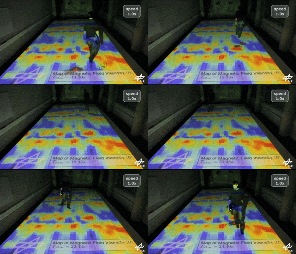
Geomagnetic positioning is one more promising indoor navigation technology. For years, people have discussed positioning using local disturbances in Earth’s magnetic field, as illustrated in Figure 6. 

There are some prototypes available, but it remains challenging to find working, affordable, and effective geomagnetic indoor navigation systems.

 Geomagnetic positioning example, as one of the indoor positioning system types  Geomagnetic positioning principle demonstration
a) Earth geomagnetic field disturbances could be used for indoor navigation. b) Geomagnetic positioning principle demonstration.

Figure 6: Geomagnetic positioning

The issues of implementation include the permanent change of the Earth’s magnetic field and perturbations caused by electric wires inside the building, among others.

Indoor Navigation Technology: Pros & Cons of Geomagnetic Positioning

Geomagnetic measurements

Advantages
Disadvantages
  • Can use mobile phones and tablets as navigation terminals.
  • Unstable accuracy: measurements can be distorted by the electric wires and changes in the Earth’s magnetic field.

Conclusion: Promising technology, but still in the experimental phase.

5. Ultra Wide Band (UWB): Indoor Navigation Service

Ultra Wide Band (UWB) indoor navigation systems utilize the beneficial feature of UWB signals, which easily penetrate through walls, human bodies, and other obstacles.

Therefore, unlike the narrow-band reference signals (Wi-Fi or Bluetooth), the UWB navigation signal, which spans a range of frequencies from several hundred MHz to several GHz, requires fewer beacons to cover a given area inside the building. 

Especially when there are numerous obstacles within, measuring the phase of the receiving UWB signal allows one to determine a distance with high accuracy (up to several centimeters). 

For extra information, you can also check a few interesting videos about UWB INS available here and here.

One example of the discussed system is KIO RTLS (Real-Time Location System), utilizing UWB anchors, as shown in Figure 7.

Example of indoor navigation service: UWB beacons

Figure 7: UWB beacons

Indoor Navigation Technology: Pros & Cons of Ultra Wide Band

UWB indoor navigation system

Advantages
Disadvantages
  • High accuracy (tens centimeters).
  • UWB indoor navigation systems are not affected by walls, human bodies, or other obstacles.
  • Require special equipment.
  • High cost

Conclusion: UWB INS belongs to professional equipment. They found a use for some critical services, for example, tracking service personnel or essential medical equipment in hospitals.

More details about the UWB indoor navigation service are available at Pozyx.

6. Ultrasonic Indoor Navigation System

Ultrasonic INS demonstrates an accuracy of several centimeters. Ultrasonic systems can also utilize the trilateration principle, as Wi-Fi INS does. 

However, the primary advantage is a lower signal propagation speed. For instance, the sonic velocity in the standard day atmosphere is about 343 meters per second. One could compare it with 300,000,000 meters per second for radio waves. 

The lower wave propagation speed results in higher indoor localization accuracy.  Thus, the distance between the target (ultrasonic receiver) and reference points can be evaluated at a low error level of 1-2 cm.


Figure 8. Receiver in the Ultrasonic indoor navigation system

Figure 8: Receiver in the ultrasonic  INS


One of the known implementations of the ultrasonic INS utilizes a GPS-like coordinate measurement algorithm that is scaled for a single-room environment. Ultrasonic Beacons, like satellites, give reference signals to the receiver. 

Arrival time defines the delay and, correspondingly, the distance. Satellites use ultra-precise atomic clocks, and ultrasonic beacons utilize a special router to synchronize time through the radio channel. 

Using the multilateration principle, as shown in Figure 2, it is straightforward to convert measured distances to user coordinates within the building. 

Pros & Cons of Ultrasonic Indoor Navigation System


Ultrasonic indoor navigation system

Advantages
Disadvantages
  • High accuracy of around tens of centimeters.
  • UWB INS are insensible to walls, human bodies, and other obstacles.
  • Special equipment is needed; see Figure 8.
  • Limited range of around 10 to 50 meters.
  • The line of sight requirement must be fulfilled.
  • Accuracy depends on air temperature fluctuations.

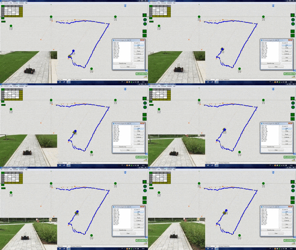
Conclusion: Ultrasonic indoor navigation systems are more suitable for navigating mobile robots, as shown in Figure 9, in medium-sized areas of around hundreds of square meters.


Figure 9. Mobile robot with ultrasonic indoor navigation technology

Figure 9: Mobile robot with ultrasonic navigation

For more information, follow these resources: Marvelmind Robotics and the Cricket Indoor Location System.

7. Indoor Navigation Service using Bluetooth Low Energy (BLE) Beacons

Bluetooth Low Energy (BLE) beacons are very promising as an indoor navigation technology. It supposes only one-way communication between the small radio transmitting devices (Beacons) and mobile devices.

Hence, the BLE devices require only small batteries to operate for 2-3 years.


Bluetooth beacons technology components

Figure 10: Bluetooth beacons technology components

Figure 10 shows some main components of the Beacons. For more details about Bluetooth Beacon hardware, you can read Aislelabs, offering a wide variety of Beacon shapes and models, as can be seen in Figure 11.


BLE Beacon devices

Figure 11: BLE Beacon devices

The iBeacon utilizes Bluetooth 4 Low Energy standard packets for broadcasting navigation information, as shown in Figure 12.


iBeacon data structure

Figure 12: iBeacon data structure

BLE beacons were initially introduced in 2013 with the launch of the iBeacon standard by Apple. This standard is proprietary, allowing only one type of advertisement packet, which consists of the parts you can see in Figure 11.

Next, the AltBeacon standard was introduced. It was created as an open alternative to the iBeacon and designed to be compatible with it.

In 2015, Google introduced the Eddystone standard. Unlike iBeacon and AltBeacon, it supports three types of packages:

  1. Eddystone-UID (user ID).
  2. Eddystone-URL.
  3. Eddystone-TLM (telemetry).

Initially, Bluetooth beacons were designed only for raw user localization and sending push notifications when a user reaches some “checkpoint”. Further development of this indoor navigation technology has unleashed its potential. 

The precision of user localization has significantly increased. Many companies have developed their SDKs (software development kits) to enable mobile application development for user navigation with Bluetooth beacons. Check out one of the examples here.

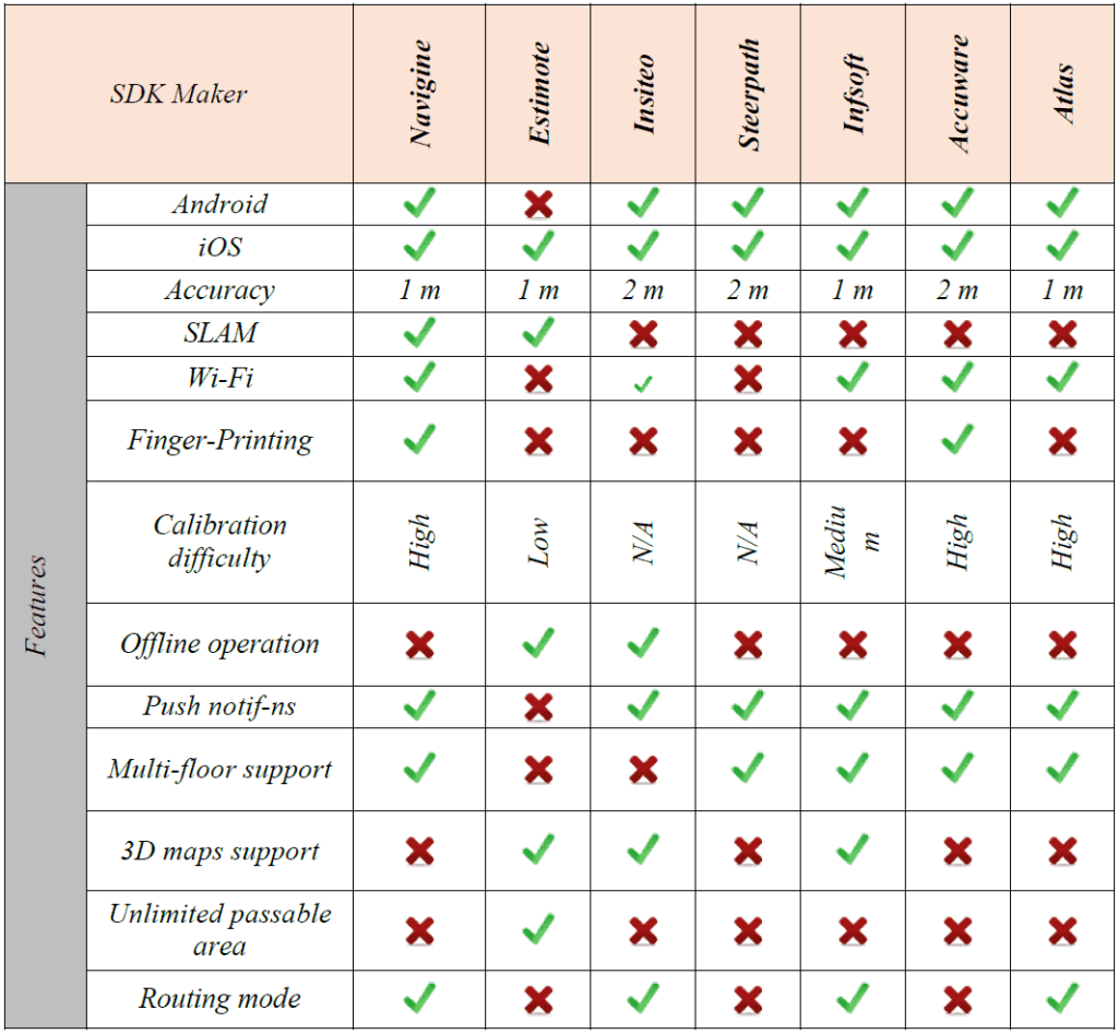
In Table 1, you can check out a brief overview of the existing SDKs and their key features.

Comparison of popular existing indoor SDKs


 Indoor Navigation Technology: Pros & Cons of Beacons

Beacon

Advantages
Disadvantages
  • Enough accurate navigation up to 1 meter.
  • Can use mobile phones and tablets as navigation terminals.
  • Cheap.
  • Simple system installation and maintenance.

Conclusion: Beacons are one of the most universal and promising techniques to build an indoor navigation service.

Industries that Benefit from Indoor Navigation Technologies

Every industry uses technology to tackle specific challenges and improve user experience. Indoor navigation systems can be utilized across a wide range of industries, for instance:

  • Retail: store locator, product navigation, promotions.
  • Healthcare: find your way around departments, track staff and equipment.
  • Logistics & Warehousing: pick-path optimization, inventory tracking, asset location.
  • Transport Hubs: terminal navigation, gate info, baggage claim directions.
  • Manufacturing: navigation to workstations, tool tracking, emergency routing.
  • Colleges & Universities: class, office, or lab navigation, event wayfinding.
  • Office Buildings: meeting room finder, visitor guidance, desk booking.

Let’s discover how these different sectors are putting it to work:

1. Retail

The use of indoor navigation systems in big shopping malls and department stores enables visitors to locate stores and product areas as well as services, including restrooms and food courts. 

Through indoor navigation, management gets real-time customer information. Retailers can enhance their store layouts and launch targeted promotions. They can send location-based push notifications and offer personalized experiences. This increases customer satisfaction and drives sales.

2. Healthcare

Usually, navigating medical institutions can be stressful. Don’t you agree? Indoor navigation systems help patients and visitors find their way around these buildings. This system reduces delays and lowers the chances of missed appointments.

Healthcare providers can use indoor navigation to:

  • Track medical equipment.
  • Watch staff movement.
  • Improve emergency response.

This way, you can boost operational efficiency and keep patients safe.

3. Warehousing

Indoor navigation technology enables workers to locate inventory items quickly and enhances packing processes. These systems can integrate with warehouse management software.

They update routes in real-time when inventory changes. Such a system improves accuracy and cuts labor costs. They also assist in asset tracking and ensure safer, more organized operations.

4. Manufacturing

In large factories, indoor navigation helps keep track of workers, tools, and materials in real time. It can guide workers to maintenance points or workstations. It also improves coordination during shift changes and reduces downtime. Such visibility contributes to higher productivity and better compliance with safety protocols.

5. Universities

The system of indoor navigation enables students, staff members, and visitors to locate classrooms, lecture halls, labs, and offices throughout extensive campus areas. 

The system can integrate with class schedules to provide users with directions to their upcoming destination. For institutions, this enhances campus accessibility and student satisfaction.

6. Office Buildings

Indoor navigation in offices enables employees and guests to find their way easily. This is especially useful in large or shared buildings. It can guide users to meeting rooms, departments, or desks in workspaces. 

Facilities managers can also use space usage data. This helps them improve layouts and manage building resources better.

7. Transport Hubs

Indoor navigation is crucial in busy transit areas. Travelers need to find gates, check-in counters, lounges, or baggage claim areas. Real-time updates and dynamic routing help minimize missed connections and passenger flow.

For airport operators, it offers insights into congestion areas and improves crowd management.

How It-Jim Helps Build Smart Indoor Navigation Solutions 

At It-Jim, we turn complex indoor spaces into intuitive, data-driven environments with advanced indoor navigation solutions.

With expertise in computer vision, mobile app development, and AI, we help businesses across industries deliver seamless navigation experiences tailored to their needs. 

1. Computer Vision for Spatial Understanding

Our team uses cutting-edge computer vision (CV) to map and interpret indoor spaces accurately. Computer vision enhances indoor navigation systems by enabling visual positioning, object recognition, and real-time mapping.

Here are some of the possible CV use cases:

  • Visual Positioning: Uses camera input to map the environment and track movement in real-time, ideal for GPS-denied areas.
  • Object & Landmark Recognition: Detects signs, doors, or logos to anchor user location and provide context-aware navigation.
  • 3D Space Reconstruction: Builds accurate 3D maps of indoor spaces to enhance routing and obstacle detection.
  • AR Navigation: Overlays visual directions (e.g., arrows, markers) onto the real world via smartphones or AR glasses.
  • Behavior & Flow Analysis: Tracks user movement to identify patterns, optimize layout, and improve space utilization.
  • Specialized Tracking: Enables real-time identification of people, assets, or animals in use-specific environments like hospitals or labs.

So, from visual SLAM (Simultaneous Localization and Mapping) to object recognition and AR overlays, we develop intelligent systems that adapt to dynamic environments, enabling real-time spatial awareness. 

2. Advanced Mobile Applications on iOS

We offer iOS development services, creating mobile apps that serve as the core interface for an indoor navigation system.

These iOS apps guide users with real-time directions, interactive maps, and personalized content – all while integrating with your existing infrastructure and branding. The iPhone’s advanced sensor suite, which includes cameras and LiDAR, enables powerful indoor positioning and navigation capabilities.

The system works best in areas where GPS signals are unavailable, such as multi-level parking lots, office complexes, and exhibition venues.

With the addition of an AR layer and 3D reconstruction on iOS, the iPhone becomes a gateway to immersive experiences, blending physical and digital spaces.

3. AI-Driven Solutions

We use AI and machine learning to power features like predictive routing, crowd flow analysis, and behavior-based personalization. This way, you enhance the user experience and provide organizations with valuable insights for operational optimization and decision-making. 

You run a hospital, airport, shopping center, or campus – the goal is to make indoor spaces as navigable, safe, and efficient as the digital world.


Looking for a partner to develop a smart indoor navigation service?

Let’s talk about how we can bring seamless navigation to your indoor space. Build custom high-performance indoor navigation systems that improve user experience and operations and unlock spatial insights for your business.

Contact us.


Challenges in Indoor Navigation Implementation

While indoor navigation systems offer significant advantages, deploying them effectively presents several challenges that organizations must consider.

1. Signal Interference and Accuracy

Indoor environments are full of obstacles like walls, ceilings, furniture, and even people that can interfere with signals from Wi-Fi, Bluetooth beacons, or other indoor positioning technologies.

These barriers can affect location accuracy and lead to a poor user experience. Environments with high metal content or electronic noise (like warehouses or hospitals) are more prone to interference.

Solution: Use hybrid systems (e.g., BLE + inertial sensors) and smart signal calibration.

2. Infrastructure Costs

Setting up an indoor navigation system requires an upfront investment in hardware, such as beacons, sensors, or cameras, and integration with mobile apps or facility management systems.

In large or older buildings, retrofitting infrastructure can be time-consuming and expensive, making ROI a concern for some organizations.

Solution: Start with high traffic areas first, scale gradually, and consider cloud-based or modular solutions.

3. System Maintenance and Support

Maintaining system accuracy over time requires regular calibration, software updates, and hardware replacement.

For example, dead batteries in Bluetooth beacons or changes in physical layout can degrade performance. Without dedicated resources, even the best systems can become unreliable quickly.

Solution: Automate diagnostics, use centralized dashboards, and schedule proactive maintenance.

4. Data Privacy and Security

The collection of precise location data by indoor navigation systems creates privacy issues and data protection concerns for users. Your organization must comply with data regulations (such as GDPR) while establishing robust security protocols to prevent unauthorized data breaches or misuse.

Solution: Implement encryption, access controls, and ensure compliance with data protection laws.

5. User Adoption and Training

Even the most advanced indoor navigation systems are only effective if users know how to use them. Ensuring adoption may require onboarding efforts, clear signage, and user-friendly interfaces, especially in public spaces or among non-tech-savvy users.

Solution: Provide clear signage, an intuitive app design, and short onboarding tutorials or demos.

Future Trends in Indoor Navigation Service 

The development of indoor navigation systems advances through emerging technologies, which create more intuitive and immersive experiences. 

The following trends will define the future development of indoor positioning services:

1. AI Integration for routing and personalization

AI analyzes patterns to predict congestion, personalize routes, and enhance accuracy in dynamic environments. AI also improves positioning accuracy by adapting to dynamic environments and learning from historical data.

2. Augmented Reality (AR) Navigation for immersive visual guidance

AR indoor navigation is changing how users interact with rooms and buildings. Instead of following a 2D map, users get visual cues like arrows, signs, or avatars overlaid in their real world via a smartphone camera or AR glasses.

3. Sensor Fusion for more precise positioning 

BLE, Wi-Fi, UWB, LiDAR, and IMUs can be combined for seamless and robust navigation even in complex buildings. This “sensor fusion” approach provides robust navigation and seamless transitions between indoor and outdoor environments.

4. Voice-Assisted Navigation for hands-free, on-demand directions

As smart assistants and wearables become more common, voice-controlled indoor navigation is gaining traction. Users will be able to ask for directions or information verbally, making it perfect for hands-busy scenarios in healthcare, logistics, and manufacturing, as well as for use with AR glasses.

5. Digital Twins & 3D Mapping for real-time spatial intelligence

3D models are interactive for real-time route planning, space monitoring, and facility management. This means dynamic updates, real-time route optimization, and facility management, particularly in large spaces such as stadiums, malls, or industrial sites.

These are not just making wayfinding better – they’re redefining how we interact with physical spaces. As AI, AR, and IoT technologies mature, indoor navigation services will become more adaptive and predictive.

Summary of Indoor Navigation Systems

The table below provides a summary of the indoor mapping technologies we have discussed. 

As showcased, the price of the BLE beacons starts at $ 10-$ 15, which is definitely the lowest in our overview. BLE beacons are a cheaper, more universal, and promising technology for the future of indoor navigation systems.

Data sources of indoor navigation technologies

On the other hand, there’s no one-size-fits-all. The best solution depends on your project’s needs, accuracy requirements, and infrastructure.

Challenges such as maintenance and setup costs, AI, sensor fusion, and AR services are helping to overcome these limitations. 

From airports and hospitals to retail stores and universities, indoor navigation systems are transforming the way people navigate complex indoor spaces, making navigation easier, safer, and data-driven.

Use our expertise in AI, computer vision, and mobile apps to create intuitive indoor navigation experiences.

Interested readers can look at the references below.

REFERENCES

[1] Ievgen Gorovyi, Alexey Roenko, Alexander Pitertsev, Ievgen Chervonyak, Vitalii Vovk, “Real-Time System for Indoor User Localization and Navigation using Bluetooth Beacons”, Proc. of the 2017 IEEE First Ukraine Conference on Electrical and Computer Engineering (UKRCON), Kyiv, Ukraine, 2017.

[2] A. Norrdine, “An Algebraic Solution to the Multilateration Problem”, Proc. of the 3rd Internat. Conf. “Indoor Positioning and Indoor Navigation”, Sydney, Australia, 2012.

[3] M. Kaustinen, M. Taskinen, T. Säntti, J. Arvo, T. Lehtonen, “Map Matching by Using Inertial Sensors”, Literature Review of University of Turku Technical Reports  No. 6,  Turku,  Finland, 2015.

[4] A. Thiagarajan, “Probabilistic, “Models For Mobile Phone Trajectory Estimation”, Thesis of master’s degree of Doctor of Philosophy in Computer Science and Engineering, Massachusetts Institute Of Technology,  Cambridge, USA, 2011.

[5] S.F. Persa, “Sensor Fusion in Head Pose Tracking for Augmented Reality”, Thesis of master’s degree in Delft University of Technology, Delft, Netherlands, 2006.

Marker-Based Augmented Reality

Augmented Reality (AR) is one of the most popular and challenging fields in computer vision research. It allows supplementing the real world with some kind of digital content, for example, virtual 3D objects. The key feature of Augment Reality in comparison to other image processing tools is that virtual objects are moved and rotated in 3D coordinates instead of 2D image coordinates.

The main objectives of AR are the analysis of changes in the captured camera frames and the correct alignment of the virtual data into the camera scene based on the tracking results. In turn, a marker-based approach provides accurate tracking using visual markers, for instance, binary markers (designed by ARUCO, METAIO, etc.) or photos of real planar objects in a camera scene.

AR tracking with different markers fig1

Fig. 1. Binary markers: ARUCO (left) and Metaio (right)

The simplified scheme of the Augment Reality system is as follows

AR tracking with different markers fig2

Fig. 2. AR system flowchart

Let’s consider AR system flowchart in details.

At first, we need to have the marker image and extract the consecutive camera frames. The tracking module in flowchart (Fig. 2) is the core of the augmented reality system. It calculates the relative pose of the camera based on correctly detected and recognized marker in the scene. The term “pose” means the six degrees of freedom (DOF) position, i.e. the 3D location and 3D orientation of an object. The tracking module enables the system to add virtual components as a part of the real scene. And since we’re dealing with camera frames in 2D coordinates system, it is necessary to use the projective geometry for virtual 3D object augmentation.

Detection and recognition

 In the case of tracking by binary marker, the first necessary thing is to print the desired marker and place it in front of the camera. This requirement is an evident drawback of the tracking algorithm.

The algorithm of detection is very simple and based on the marker nature:

  • Application of adaptive thresholding to extract edges;
  • Extraction of closed contours from the binary image;
  • Filtration of contours;
  • Contours approximation and detection of quadrilateral-shaped contours.

After the above steps, the marker candidates are stored for further marker recognition.

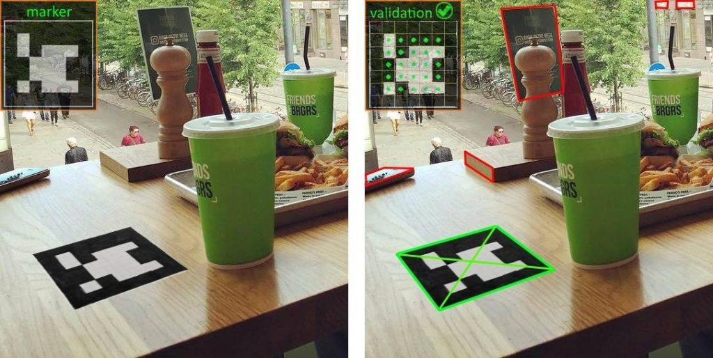
Each candidate is warped to the frontal view and divided into blocks. The task of the recognition algorithm is to extract binary code from the marker candidate and compare it with the code of the true marker. The most similar candidate is considered a matched marker.

AR tracking with different markers fig3

Fig. 3. Scene with a binary marker (left) and detected marker(right)

Fig.3 illustrates an example of the scene and how the detection and recognition of the binary marker is accomplished.

The more advanced tracking algorithm by the photo marker allows getting rid of placing synthetic binary markers in the scene. It is enough just to take a picture of a planar object in a real scene and use it as a marker.

The methods based on the local features are the most common to this task. Good candidates for such tasks are robust SURF [1] descriptors or one of the binary descriptors: ORB [2], FREAK [3], BRIEF [4], BRISK [5], or LATCH [6]. The matching of local descriptors is typically done using a common Brute Force matcher or with a more efficient FLANN algorithm. As a result, after matching the data augmentation can be done. A high-level scheme of such a process is given below

AR tracking with different markers fig4

Fig. 4. Algorithm of image-based tracking

This method also has some disadvantages. It really resource-intensive over a large number of computations on stages of feature detection, calculation of descriptors and feature matching. Nevertheless, our team has developed a robust tracking algorithm with real-time performance.

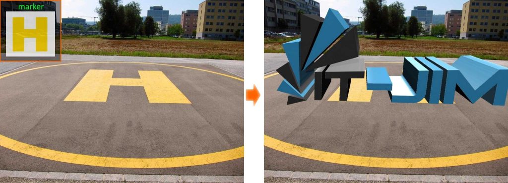
The example of the augmentation of a virtual object with a real planar marker in the scene is represented in figure 5.

AR tracking with different markers fig5

Fig. 5. Augmentation result

References:

[1] Bay, H., A. Ess, T. Tuytelaars, and L. Van Gool. “SURF: Speeded Up Robust Features.” Computer Vision and Image Understanding (CVIU).Vol. 110, No. 3, pp. 346–359, 2008.

[2] Rublee, Ethan, et al. “ORB: an efficient alternative to SIFT or SURF.” Computer Vision (ICCV), 2011 IEEE International Conference on. IEEE, 2011.‏

[3] Alahi, Alexandre, Raphael Ortiz, and Pierre Vandergheynst. “Freak: Fast retina keypoint.” Computer Vision and Pattern Recognition (CVPR), 2012 IEEE Conference on. IEEE, 2012.‏

[4] Calonder, Michael, et al. “Brief: Binary robust independent elementary features.” Computer Vision–ECCV 2010. Springer Berlin Heidelberg, 2010. 778-792.‏

[5] Leutenegger, Stefan, Margarita Chli, and Roland Y. Siegwart. “BRISK: Binary robust invariant scalable keypoints.” Computer Vision (ICCV), 2011 IEEE International Conference on. IEEE, 2011.‏

[6] Gil Levi and Tal Hassner, LATCH: Learned Arrangements of Three Patch Codes, IEEE Winter Conference on Applications of Computer Vision (WACV), Lake Placid, NY, USA, March, 2016.

Tesseract Library Configuration

Tutorial for Installing Tesseract

You’ve undoubtedly seen it before… It’s widely used to process everything from scanned documents to the handwritten scribbles on your tablet PC and Google Translate. And today you’ll create your first app for text recognition.

What is OCR?

Optical Character Recognition, or OCR, is the process of electronically extracting text from images and reusing it in a variety of ways such as document editing, free-text searches, or compression. In this tutorial, you’ll learn how to install Tesseract, an open-source OCR engine maintained by Google.

How to Install Tesseract for Microsoft Visual Studio?

Step 1:

To install Tesseract you need to install the following programs:


git

https://git-scm.com/
 

slik-svn

https://www.sliksvn.com/en/download
 

visual-studio

https://www.visualstudio.com

Step 2:

What’s next? That’s right, create a folder where we want to install Tesseract. This can be any directory on your computer, for example: “D:\Tesseract-files”.
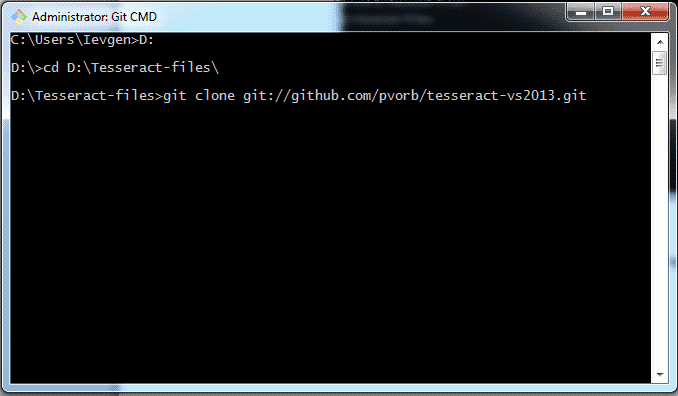
After that, run GIT CMD and move to Tesseract`s folder. Your GIT command line should look like this:

Installation Tesseract. Picture 1

Fig. 1. GIT CMD example

Step 3:

Now you need to copy the entire dependency from the GitHub repository to your computer. To do this, we write the following command in GIT CMD:
git clone git://github.com/pvorb/tesseract-vs2013.git. In the console GIT CMD you will see something like this:

Installation Tesseract. Picture 2

Fig. 2. Clone tesseract-vs2013.git

After executing this command, you will see the following in the console:

Installation Tesseract. Picture 3

Fig. 3. Clone tesseract-vs2013 done

Step 4:

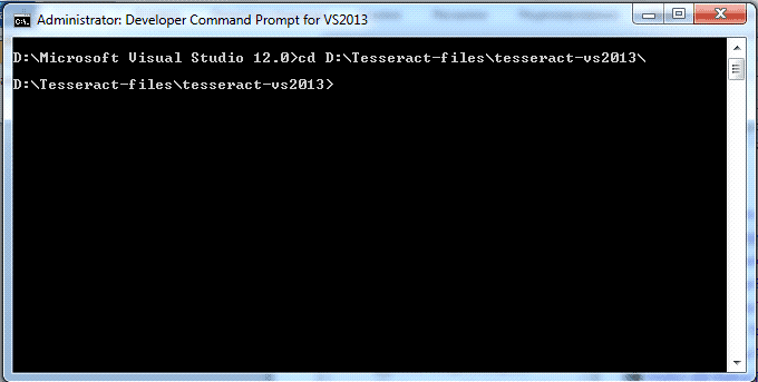
For the next step, run VS2013 developer command Prompt. It is in: {directory of MS VS}\Common7\Tools\Shortcuts\Developer Command Promt VS2013. And move to D:\Tesseract-files\tesseract-vs2013.

Installation Tesseract. Picture 4

Fig. 4. Command promt for VS2013

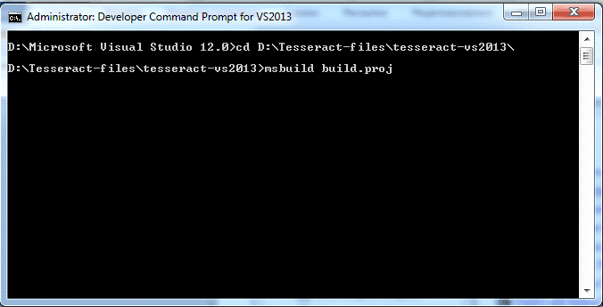
Now we can perform building using the command msbuild build.proj: 

Installation Tesseract. Picture 5

Fig. 5. Start performing build

After this step, the VS2013 can be closed.

Step 5:

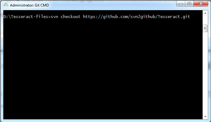
Reopen GIT CMD and check folder and check the working directory. Must be “D:\Tesseract-files\”.  After that, gets the latest source using SVN (print in GIT CMD):   svn checkout https://github.com/svn2github/Tesseract.git.

Installation Tesseract. Picture 6

Fig. 6. Checkout Tesseract

After performing this procedure, the new folder appears in a folder D:\Tesseract-files\ which name is Tesseract.git\.
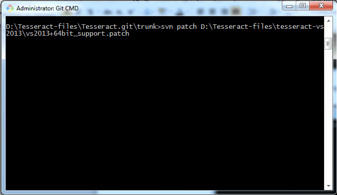
Move in GIT CMD to D:\Tesseract-files\Tesseract.git\trunk and apply the patch provided in tesseract-vs2013 (print in cmd): svn patch D:\Tesseract-files\tesseract-vs2013\vs2013+64bit_support.patch

Installation Tesseract. Picture 7

Fig. 7. Patch provided in tesseract-vs2013

Copy both directory (lib and include) from D:\Tesseract-files\tesseract-vs2013\release into D:\Tesseract-files\Tesseract.git\trunk\
Open D:\Tesseract-files\Tesseract.git\trunk\vs2013\tesseract.sln with Visual Studio 2013.

Step 6:

Open Property pages of libtesseract304 and in Configuration Properties->C/C++->General->Additional Include Directories  add D:\Tesseract-files\Tesseract.git\trunk\include\  and D:\Tesseract-files\Tesseract.git\trunk\include\ leptonica\; In Property  pages open Linker->General->Additional Library Directories add D:\Tesseract-files\Tesseract.git\trunk\lib\x64\;
It is necessary to repeat this operation for Debug and Release. Build the project in Release and Debug.

Step 7:

What would Tesseract recognized the text he needs training files. They can be found in: https://github.com/tesseract-ocr/tessdata. Download the necessary files and copy them to D: \Tesseract-files\Tesseract.git\trunk\ tessdata\

Step 8:

Copy tesseract`s .dll files to necessary project from D:\Tesseract-files\Tesseract.git\lib copy libtesseract304.dll (or libtesseract304d.dll) to Release (or Debug) folder in necessary project (In this folder must be exe file).From D:\Tesseract-files\tesseract-vs2013\lib\x64 (or X64) copy liblept171.dll (or liblept171d.dll) to Release (or Debug) folder in necessary project (In this folder must be exe file).

Connect Tesseract into project (is necessary for Debug and for Release).

Set properties of necessary project:

  in C/C++ –> General –> Additional Include Directories:
D:\Tesseract-files\Tesseract.git\trunk\
D:\Tesseract-files\Tesseract.git\trunk\ccmain
D:\Tesseract-files\Tesseract.git\trunk\ccstruct
D:\Tesseract-files\Tesseract.git\trunk\ccutil
D:\Tesseract-files\Tesseract.git\trunk\leptonica
D:\Tesseract-files\Tesseract.git\trunk\api
D:\Tesseract-files\Tesseract.git\trunk\include

In Linker –> General –> Additional Library Directories:
D:\Tesseract-files\Tesseract.git\lib\x64
D:\Tesseract-files\Tesseract.git\lib\

In Linker –> Input –> Additional Dependencies:

for Debug

libtesseract304d.lib
liblept171d.lib

for Release

libtesseract304d.lib
liblept171d.lib.

Step 9:

So, create new console application and paste this code:

#include “baseapi.h”

#include “allheaders.h”

int main()

{

                char *outText;

                tesseract::TessBaseAPI *api = new tesseract::TessBaseAPI();

                // Initialize tesseract-ocr  with English, without specifying tessdata path

                if (api->Init(“D:\\Tesseract-files\\Tesseract.git\\trunk”, “eng”)){

                               fprintf(stderr, “Could not initialize tesseract.\n”);

                               exit(1);

                }

                // Open input image

                Pix *image = pixRead(“yout_image.tif”);

                api->SetImage(image);

                // set list of allowed characters

                api->SetVariable(“tessedit_char_whitelist”, “abcdefghijklmnoprstuvwxyzABCDEFGHIJKLMNOPQRSTUVWXYZ-.;,:/0123456789”);

                // Get OCR result

                outText = api->GetUTF8Text();

                printf(“OCR output:\n%s”, outText);

                // Destroy used object and release memory

                api->End();

                delete[] outText;

                pixDestroy(&image);

return 0;

}

Then build and compile the project.

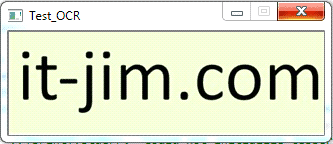
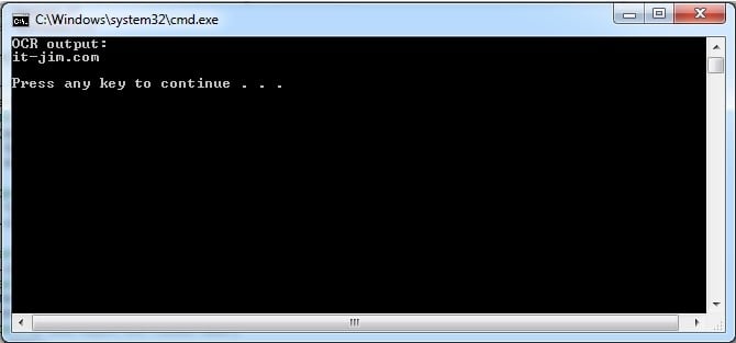
As a result, you will get:

Installation Tesseract. Picture 8

Fig.8. Input image


Installation Tesseract. Picture 9

Fig. 9. Output result


Congratulation! You installed and started your first text recognition program!

Automatic Number Plate Recognition (ANPR) Systems

Currently, the number of cars in the world is well over 1 billion. It is no wonder that one of the most common computer vision tasks is the effective control of these vehicles through automatic number plate recognition (ANPR) systems. The applications of automatic vehicle number plate detection and recognition vary depending on the area of use and include, among others, border control, stolen car detection, automatic ticketing of vehicles and toll collection, traffic monitoring and safety control, smart parking, tracking of transportation, etc.

A typical automatic number plate recognition algorithm includes several steps (Fig. 1): car license plate detection (1), character segmentation (2) and recognition (3).

Vehicle number plate recognition algorithm
Fig. 1. Main steps of ANPR

Within this vehicle number plate recognition project, we concentrated on the first step of the algorithm: locating the area on the image that corresponds to the license plate number. It is indeed a crucial step of the whole recognition pipeline since it strongly affects the overall system performance.

As the first step of the project, we extracted the plate candidates areas based on the following two approaches:

  • stroke width transform (SWT), which was used to locate the image regions containing the text);
  • blob detection algorithm, which increased the final detection rate.

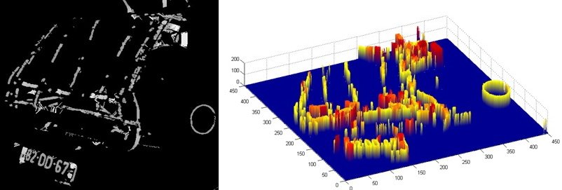
The SWT is a well-known text detection algorithm. The idea lies behind the careful analysis of the image edge map and local gradient directions. The basic preparation steps include the calculation of the Sobel gradients and Canny edge map construction.

The results of SWT application to the image and its 3D view are illustrated in Fig. 2.

                                                                                     Car plate recognition system - SWT algorithm

Fig. 2. SWT image example

Read also:

Road Detector

To locate the text region on the image, which corresponds to the vehicle number plate, we proceed with the following steps:

License Plate Recognition - Steps

To increase the rate of the vehicle number plate detection, we have additionally integrated the blobs analysis procedure, which is based on morphological operators and contours calculation and applied to the preprocessed images. Fig. 3 illustrates an example of found number plate candidates using the developed method.

license plate recognition - an example of using the method

Fig. 3. Detected blobs and bounding boxes

The combination of SWT and blob detection approaches returns the list of the number plate candidates. The final step of the project was to extract the true car license plate area.

For this, we used a 3-layer perceptron neural network (NN) which classifies the obtained sequence of number plate candidates. The NN was trained using different sets of features including:

  • Haar-based features (based on integral images);
  • statistical features (mean, std, skewness);
  • principal component analysis (PCA) features.

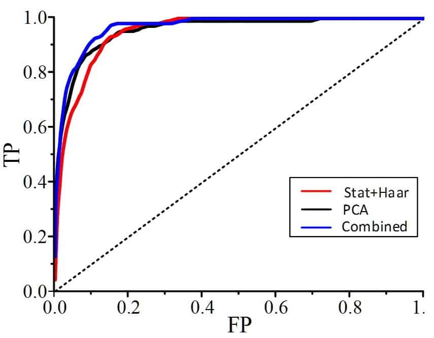
Fig. 4 demonstrates an example of the obtained receiver operating characteristics (ROC) curves for three different learning scenarios. The ROC curve represents the dependence of true positive rate (TP) on the false positive rate (FP).

Number plate identification system - ROC curves
Fig. 4. ROC curves for different sets of features

The best classification results are obtained when using a combination of all three groups of features for NN training.

Our paper which describes the above-mentioned results in more detail was presented at the Signal Processing Symposium 2015 where it received the 1st prize for the best publication.

The ANPR pipeline discussed in this post is an open-ended research task and all steps can be further improved, however, it proves that CNN is not the only solution for solving such kind of tasks.