Segmentation Guide for iOS: Top 4 Models in 2026

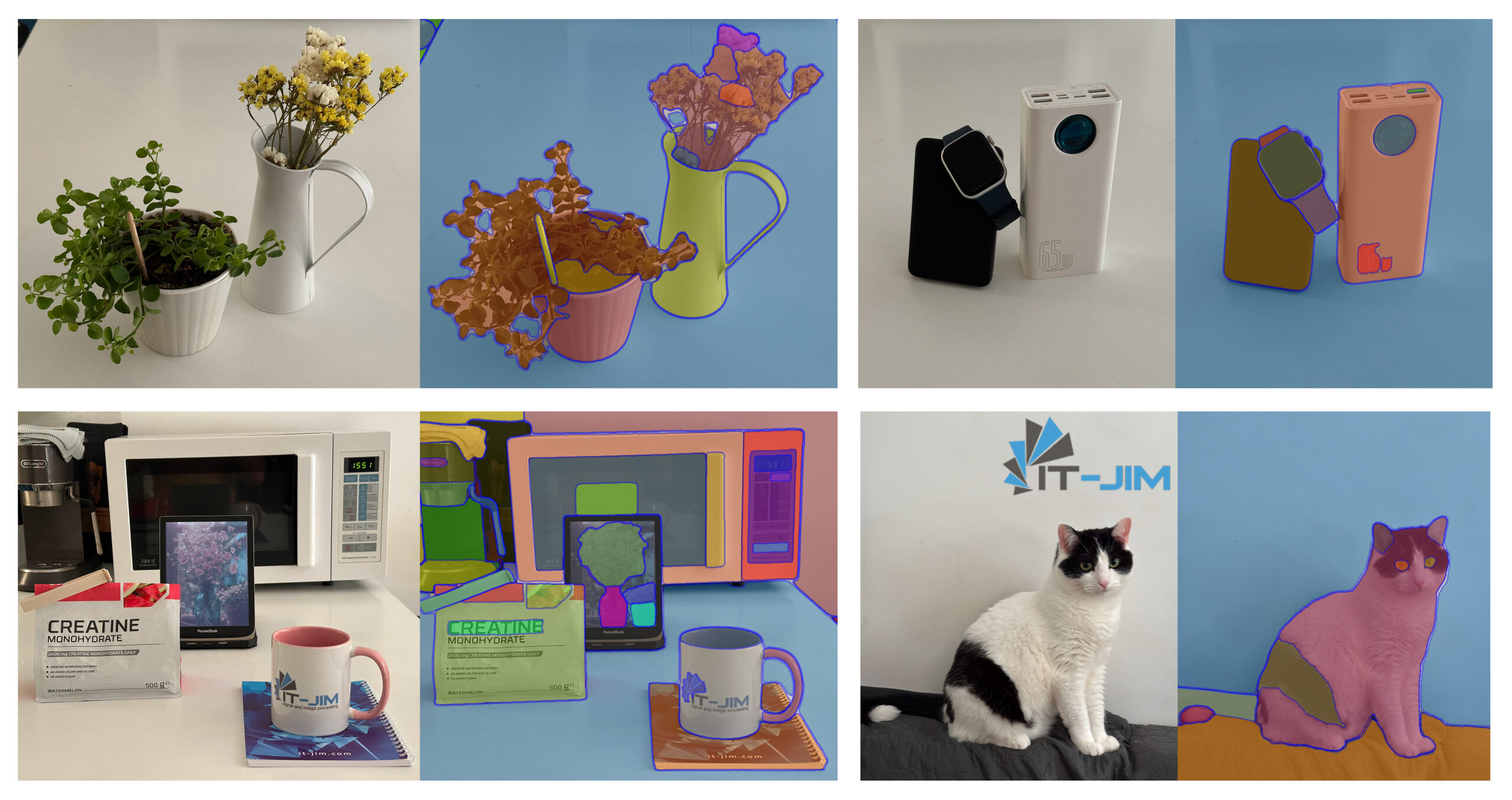
Segmentation has quietly become one of the most useful tools in modern tech. Whether it’s helping doctors analyze medical images, powering AR effects, tracking objects, or making photo editing smarter, segmentation plays a key role behind the scenes.

By identifying and isolating objects or regions within an image, it unlocks powerful capabilities that enhance user experiences across industries.

Businesses leverage segmentation in a variety of ways: beauty and fashion apps use it for virtual try-ons, fitness apps analyze body posture, e-commerce platforms enable interactive product previews, and accessibility tools detect and describe visual content for users with impairments.


With the growing performance of mobile devices and the support of Core ML, segmentation is no longer limited to server-side processing. iOS developers can now integrate advanced segmentation models directly into their apps.

This article explores segmentation for iOS development, covering how it works, the best models for integration, their limitations, and implementation tips.

Segmentation on iOS: How It Works

Segmentation involves partitioning an image into multiple segments or regions, each representing meaningful areas such as objects, backgrounds, or boundaries.

Unlike simple object detection, which only provides bounding boxes, segmentation offers pixel-level understanding of the scene. This fine-grained information is crucial for applications where precision and context matter.

The main types of segmentation are:

  • Semantic segmentation: Assigns each pixel to a class (e.g., road, sky, car). It treats all objects of the same class as identical, without distinguishing between individual instances.
  • Instance segmentation: Goes further by distinguishing separate objects within the same class. For example, it can identify two different cars instead of labeling them both simply as “car.”
  • Panoptic segmentation: Combines semantic and instance segmentation, providing a complete view where every pixel is labeled with both a class and an instance ID.
  • Interactive segmentation: Allows user input, such as clicks or strokes, to refine segmentation results, useful in photo editing and annotation tasks.

iOS offers developers a broad range of options for implementing segmentation:

  • CoreML – allows developers to integrate custom or pre-trained models optimized for iOS hardware. Many segmentation models, including DeepLab and YOLO variants, can be converted to Core ML format.
  • Vision framework – offers high-level APIs for tasks such as object detection and person segmentation.
  • ARKit provides built-in segmentation for AR applications, specifically, people occlusion.

Apart from native solutions, there are several popular segmentation architectures used today, such as DeepLab, Mask R-CNN, U-Net and its variants, HRNet, YOLO models with segmentation heads, SAM (Segment Anything Model), and FastSAM.

Segmentation on iOS: Top 4 Models

With this variety, choosing the right segmentation approach depends on accuracy requirements, model size, inference speed, and integration complexity for iOS.

For our comparison, we have selected four representative models that are widely used and relevant for mobile development:

  • SAM (Segment Anything Model) – a universal, prompt-based model.
  • DeepLab – a leading semantic segmentation architecture.
  • YOLOv11 – a fast real-time instance segmentation model.
  • FastSAM – a lightweight prompt-based segmentation model.

Let’s start examining these options for segmentation on iOS in greater detail.

1. DeepLabV3

DeepLab, developed by Google, is one of the most established and widely used models for semantic image segmentation. Over multiple versions, the model has progressively improved in accuracy and efficiency, making it a reliable choice for many applications, including on-device use.

DeepLab is effective at labeling each pixel in an image with a class label, making it ideal for applications where precise object outlines aren’t necessary but pixel-wise classification is critical. The model has been extensively studied and optimized.

On iOS devices, DeepLab models optimized for mobile deliver near real-time performance. However, DeepLab’s semantic segmentation output treats all objects of the same class as a single entity, which can be limiting for apps that require distinguishing individual objects.

Additionally, its accuracy is not always reliable, and it can produce poor-quality masks.

DeepLab Segmentation Model: Pros & Cons

Let’s look at the advantages and disadvantages of using the DeepLab model:

Advantages of the model include: 

  • Mature and well-supported, making it easier to integrate.
  • Good balance of speed, ease of integration, and accuracy.
  • The model is widely applicable.

Disadvantages of the DeepLabV3 model are as follows:

  • No instance-level segmentation. It does not differentiate between multiple objects of the same class. 
  • Performs poorly on rotated images.
  • Not suited for interactive or prompt-based segmentation. It does not support user-guided segmentation, limiting its use in applications needing dynamic, user-driven mask refinement.
  • Limited generalization outside trained classes. It performs best on categories seen during training and may struggle with novel or unusual objects.

Integration of DeepLab into iOS

To use DeepLab in your project, you need to add a Core ML version of the DeepLab model. You can find an already converted version of the DeepLab model on the Apple Developer website.

Then you can initialize the model as follows:


func initDeepLab() {
        processingQueue.async { [weak self] in
            do {
                let configuration = MLModelConfiguration()
                configuration.computeUnits = .all
            
                self?.deepLabModel = try DeepLabV3(configuration: configuration)
            } catch {
                log.error(error: error)
            }
        }
}

After initialization, you can perform predictions on images. To get a correct mask from the received multi-array output, create a CGImage mask and resize it to match the original image size.


func maskWithDeepLab(image: URL) {
        guard
            let deepLabModel,
            let inputImage = CIImage(
                contentsOf: image,
                options: [.colorSpace: NSNull()]
            ),
            let vnModel = try? VNCoreMLModel(for: deepLabModel.model)
        else {
            return
        }
        let request = VNCoreMLRequest(model: vnModel) { [weak self] request, _ in
            guard
                let self,
                let result = request.results?.first as? VNCoreMLFeatureValueObservation,
                let arrayValue = result.featureValue.multiArrayValue,
                let maskCGImage = arrayValue.cgImage(min: 0, max: 1),
                let ciImage = CIImage(
                    cgImage: maskCGImage,
                    options: [.colorSpace: NSNull()]
                ).resized(to: inputImage.extent.size)
            else {
                self?.processing = false
                self?.eventSubject.send(.failed(error: .maskingFailed))
                return
            }
            
            self.processingStage = .processingMask
            
            self.finalizeMask(input: image, mask: ciImage)
        }
        request.imageCropAndScaleOption = .scaleFill
        
        operationQueue.addOperation {
            try? VNImageRequestHandler(ciImage: inputImage).perform([request])
        }
}

2. YOLOv11

Recent versions of YOLO, including YOLOv11, introduce segmentation alongside detection capabilities, making it a versatile choice for real-time instance segmentation on mobile devices such as iPhones and iPads.

YOLOv11 is optimized for high-speed performance, capable of processing images and video streams at frame rates suitable for interactive applications.

This model uses instance segmentation and, unlike semantic segmentation models, YOLOv11 can detect and segment multiple individual objects within the same class, providing pixel-precise masks for each instance.

It also combines detection and segmentation in a single forward pass, allowing you to obtain masks along with bounding boxes. YOLO delivers quite good accuracy in both detection and segmentation tasks.

However, YOLOv11’s instance segmentation requires careful tuning of confidence thresholds and post-processing steps to ensure quality masks. Integration demands more code and additional time.

Fortunately, Ultralytics provides a YOLO Swift Package that simplifies integrating the YOLO model. With minimal code, it is possible to get all the necessary data, like an array of masks, a combined mask, bounding boxes, etc. Although the package simplifies integration, the extra processing causes a notable increase in processing time.

YOLOv11 Segmentation Model: Pros & Cons

When using the YOLOv11 model for segmentation, it’s important to consider both advantages and disadvantages.

Advantages of the model include:

  • Fast detection.
  • Instance segmentation allows for detecting and segmenting multiple individual objects of the same class, which is crucial for tasks like object counting, tracking, and interaction.
  • Unified detection and segmentation.
  • Pre-trained and widely supported.
  • Good accuracy-to-speed ratio, balancing precision and inference speed.

Disadvantages of the YOLOv11 model for segmentation:

  • Integration overhead. Handling the outputs (bounding boxes, masks, class probabilities) and converting them can be more complex than other segmentation models, or it requires external dependencies like the YOLO package.
  • The system’s performance is lower when all post-processing steps are included compared to some other segmentation solutions.

Integration of YOLOv11 into iOS

To perform segmentation with the YOLOv11 model, you need to export it in CoreML format and add the YOLO Swift Package to your project. Follow the steps in the “Export” section of the Ultralytics documentation.

Then, initialize the model as follows:

func initYOLO(modelName: String) {
        yolo = YOLO(modelName, task: .segment) { [weak self] result in
          switch result {
          case .success(_):
              self?.mlLoaded = true
  
          case .failure(let error):
              log.error(error: error)
          }
        }
}

With minimal code, you can then perform predictions on images. The model returns an array of masks along with a combined mask (which already contains all masks and their bounding boxes).

To get a mask that satisfies your requirements, you need to create a CGImage mask from the masks array and then resize it to the input image size.


func maskWithYOLO(image: URL) {
        guard
            let inputImage = CIImage(
                contentsOf: image,
                options: [.colorSpace: NSNull()]
            )
        else {
            return
        }
        operationQueue.addOperation { [weak self] in
            guard let self else {
                return
            }
            let result = self.yolo?(inputImage)
            guard
                let masks = result?.masks?.masks,
                let maskCGImage = getMask(from: masks),
                let ciImage = CIImage(
                    cgImage: maskCGImage,
                    options: [.colorSpace: NSNull()]
                ).resized(to: inputImage.extent.size)
            else {
                return
            }
            
            self.finalizeMask(input: image, mask: ciImage)
        }
}

3. SAM

The Segment Anything Model (SAM), developed by Meta AI, represents a major step forward in image segmentation.

Unlike traditional segmentation models that require training for specific classes or datasets, SAM is designed as a general-purpose, promptable segmentation model. It can generate segmentation masks for virtually any object in an image, even for categories it has never seen before, making it exceptionally versatile.

The model also supports interactive segmentation: users can refine the result by adding or removing prompts, enabling precise control. By providing points and boxes, users can obtain accurate segmentation masks quickly, making it ideal for interactive tools.

SAM is composed of three primary components that work together to produce high-quality masks:

  • Image Encoder 

It is a Vision Transformer (ViT) trained to convert the input image into a rich, high-dimensional embedding. This embedding captures spatial and semantic features at multiple levels of abstraction. The encoded image serves as the foundation for subsequent segmentation and remains unchanged regardless of prompts.

  • Prompt Encoder

It transforms user input – such as points, bounding boxes – into an embedding space that can be combined with the image representation. These embeddings are spatially aligned with the image embeddings, enabling the model to understand where segmentation should occur.

  • Mask Decoder

The Mask Decoder is a lightweight neural network responsible for predicting segmentation masks. It combines information from both the image embedding and the prompt embedding to generate accurate masks.

However, SAM is a large model by design, initially intended for cloud or desktop inference. Its standard versions are computationally intensive and require significant memory, which can be a challenge for direct on-device deployment.

To address this, lighter, optimized versions and distilled implementations have been developed, allowing SAM to run on devices like the iPhone and iPad with acceptable performance, especially when combined with Core ML optimization.

SAM consistently delivers high-quality masks across diverse domains. Its ability to generalize to unseen categories is a standout advantage, enabling robust performance even when objects are not part of the training data.


SAM: Advantages & Disadvantages of SAM

Now let’s take a closer look at the advantages and disadvantages of using SAM in iOS applications.

Advantages:

  • Universal applicability. SAM’s architecture enables segmentation of virtually any object, even categories unseen during training. 
  • Prompt-based interaction. Users can guide the model with simple prompts, such as points or boxes.
  • Zero-shot performance. No additional training or fine-tuning is required.
  • High accuracy and detail. It produces fine-grained masks that closely follow object boundaries.

Disadvantages:

  • Long model loading time. Loading all three components (image encoder, prompt encoder, mask decoder) takes noticeably more time than other models.
  • High resource consumption
  • Over-generalization. While flexible, SAM may misinterpret complex or unusual shapes, requiring manual corrections.

Integration of SAM into iOS

To integrate SAM into an iOS project, you need to add 3 CoreML models, such as SAMImageEncoder, SAMPromptEncoder, and SAMMaskDecoder.

You can find and download already converted models of different sizes in this GitHub repository.

Initially, the SAM models must be loaded. This process is asynchronous and time-consuming due to the model sizes.

func initMLModels() {
        let startTime = CACurrentMediaTime()
        Task { [weak self] in
            let configuration = MLModelConfiguration()
            configuration.computeUnits = .all
            
            let (imageEncoder, promptEncoder, maskDecoder) = try await Task.detached(priority: .userInitiated) {
                let imageEncoder = try SAMImageEncoder(configuration: configuration)
                let promptEncoder = try SAMPromptEncoder(configuration: configuration)
                let maskDecoder = try SAMMaskDecoder(configuration: configuration)
                return (imageEncoder, promptEncoder, maskDecoder)
            }.value
            
            let endTime = CACurrentMediaTime()
            let processingTime = endTime - startTime
            log.debug(message: "Model loading time for SAM - \(processingTime)")
            
            self?.imageEncoderModel = imageEncoder
            self?.promptEncoderModel = promptEncoder
            self?.maskDecoderModel = maskDecoder
            
            self?.eventSubject.send(.modelsLoaded)
        }
    }

To generate a mask, the input image must be resized to 512×512 and converted into a CVPixelBuffer.

func prepareInput(
        input: URL,
        completion: @escaping (CIImage?, CVPixelBuffer?, MaskingError?) -> Void
    ) {
        processingQueue.async { [weak self] in
            guard 
                let self,
                let inputImage = CIImage(
                    contentsOf: input,
                    options: [.colorSpace: NSNull()]
                )
            else {
                completion(nil, nil, .maskingFailed)
                return
            }
            
            let resizedImage = inputImage.resizedAndTranslated(to: MaskingConstants.inputSize)
            
            guard let pixelBuffer = self.context.render(resizedImage, pixelFormat: kCVPixelFormatType_32ARGB) else {
                completion(nil, nil, .maskingFailed)
                return
            }
            
            completion(inputImage, pixelBuffer, nil)
        }
    }

Next, the user-selected points must be encoded using SAMPromptEncoder to produce embeddings compatible with the model.

func getPromptEncoding(
        from allPoints: [SAMProcessingPoint],
        with size: CGSize
    ) async throws -> SAMPromptEncoderOutput {
        guard let model = promptEncoderModel else {
            throw MaskingError.modelNotLoaded
        }
        
        let transformedCoords = transformCoords(
            allPoints.map { $0.coordinates },
            normalize: false,
            origHW: size
        )
        let pointsMultiArray = try MLMultiArray(
            shape: [1, NSNumber(value: allPoints.count), 2],
            dataType: .float32
        )
        let labelsMultiArray = try MLMultiArray(
            shape: [1, NSNumber(value: allPoints.count)],
            dataType: .int32
        )
        
        for (index, point) in transformedCoords.enumerated() {
            pointsMultiArray[[0, index, 0] as [NSNumber]] = NSNumber(value: Float(point.x))
            pointsMultiArray[[0, index, 1] as [NSNumber]] = NSNumber(value: Float(point.y))
            labelsMultiArray[[0, index] as [NSNumber]] = NSNumber(value: allPoints[index].category.type.rawValue)
        }
        
        return try model.prediction(points: pointsMultiArray, labels: labelsMultiArray)
    }

After that, using the image and prompt encodings, we can now generate the segmentation mask.

func prepareMask(
        inputImage: CIImage,
        pixelBuffer: CVPixelBuffer,
        points: [CGPoint],
        completion: @escaping (CIImage?, MaskingError?) -> Void
    ) {
        Task {
            guard
                let imageEncoderModel,
                let imageEncoding = try? imageEncoderModel.prediction(image: pixelBuffer)
            else {
                completion(nil, .modelNotLoaded)
                return
            }
            let processingPoints = points.map { SAMProcessingPoint(coordinates: $0, category: .foreground) }
            
            let promptEncoding = try await getPromptEncoding(
                from: processingPoints,
                with: inputImage.extent.size
            )
            guard
                let maskImage = try await getCIMask(
                    originalSize: inputImage.extent.size,
                    imageEncoding: imageEncoding,
                    promptEncoding: promptEncoding
                )
            else {
                completion(nil, .maskingFailed)
                return
            }
            
            completion(maskImage, nil)
        }
    }

SAMMaskDecoder processes both encodings and produces a low-resolution mask.

func getMaskPredictions(
        imageEncoding: SAMImageEncoderOutput,
        promptEncoding: SAMPromptEncoderOutput
    ) async throws -> MLMultiArray {
        guard let model = maskDecoderModel else {
            throw MaskingError.modelNotLoaded
        }
        
        let image_embedding = imageEncoding.image_embedding
        let feats0 = imageEncoding.feats_s0
        let feats1 = imageEncoding.feats_s1
        let sparse_embedding = promptEncoding.sparse_embeddings
        let dense_embedding = promptEncoding.dense_embeddings
        
        let output = try model.prediction(
            image_embedding: image_embedding,
            sparse_embedding: sparse_embedding,
            dense_embedding: dense_embedding,
            feats_s0: feats0,
            feats_s1: feats1
        )
        return MLMultiArray(output.low_res_masksShapedArray[0, 0])
    }

Finally, when we have a multi-array output, we need to generate a mask and resize it to match the input image size.

func getCIMask(
        originalSize: CGSize,
        imageEncoding: SAMImageEncoderOutput,
        promptEncoding: SAMPromptEncoderOutput
    ) async throws -> CIImage? {
        let maskArray = try await getMaskPredictions(
            imageEncoding: imageEncoding,
            promptEncoding: promptEncoding
        )
        
        var minValue: Double = 9999
        var maxValue: Double = -9999
        
        for i in 0..<maskArray.count {
            let v = maskArray[i].doubleValue
            if v > maxValue { maxValue = v }
            if v < minValue { minValue = v }
        }
        let threshold = -minValue / (maxValue - minValue) - 0.05
        
        if let maskCGImage = maskArray.cgImage(min: minValue, max: maxValue) {
            let ciImage = CIImage(cgImage: maskCGImage, options: [.colorSpace: NSNull()])
            let resizedImage = ciImage.resized(
                to: originalSize,
                applyingThreshold: Float(threshold)
            )
            return resizedImage
        }
        return nil
    }

4. FastSAM

FastSAM is a lightweight and efficient version of Meta’s original Segment Anything Model (SAM). It is designed by Ultralytics to bring powerful segmentation capabilities to environments with limited computing resources, such as mobile and edge devices.

It aims to deliver the flexibility and accuracy of SAM’s promptable segmentation while significantly reducing inference time and computational cost, making it a strong candidate for mobile applications requiring near real-time performance.

While FastSAM retains SAM’s core strength – segmenting arbitrary objects in images – it currently does not offer a fully promptable Core ML model out of the box.

However, it is possible to export FastSAM into a Core ML format and use it like a standard segmentation model without prompts. Developers can then apply post-processing logic to filter masks based on specific regions of interest or user-defined points, simulating prompt-based behavior.

Thanks to its efficiency, FastSAM is suited for segmentation tasks on iOS, making it a practical alternative to other segmentation solutions.

While accuracy is suitable for main objects, it often produces many incorrect small masks – such as background textures, reflections, or shadows – which require additional filtering.

FastSAM Segmentation Model: Pros & Cons

Here we describe the advantages and disadvantages of using FastSAM for segmentation on iOS. Advantages include:

  • Lightweight and fast.
  • Low resource consumption.
  • Decent accuracy for masks of the main detected objects.

Disadvantages of the model are as follows:

  • Produces many incorrect small masks. Requires additional filtering.
  • Not widely tested or supported.
  • No prompatable CoreML model.
  • Requires post-processing.

Integration of FastSAM into iOS

To perform segmentation with the FastSAM model, you need to export it to Core ML format and add the YOLO Swift Package to your project. After that, predictions are made in the same way as with the YOLOv11 model.

Comparing Segmentation Models for iOS

The following table summarizes the key differences between the models to help you choose the most suitable option.

Criteria DeepLab YOLOv11 SAM FastSAM
Model type Semantic segmentation Instance segmentation Promptable general segmentation  Lightweight promptable segmentation, on iOS instance segmentation only
Accuracy Moderate (Not always accurate) Moderate-High Very high Moderate–High(good for main objects, but includes many false-positive masks)
Speed Moderate(300 ms) Slow if using YOLO package(1 s) Moderate(300 ms) Slow if using YOLO package(1 s)
Model Initialization Speed  Fast(1.4 s) Fast(1.8 s) Slow(40 s) Fast(1.6 s)
Model size Small (8.6 MB) Small (6 MB) Large (34 MB) Moderate (23.8 MB)
Resource Usage Moderate (RAM up to 650 MB,

CPU up to 110%)

Moderate (RAM up to 700 MB,

CPU up to 110%)

High (RAM up to 1000 MB, 

CPU up to 110%)

Moderate (RAM up to 750 MB, CPU up to 100%)
Ease of Integration Easy Difficult( requires handling complex outputs) /

Easy(using YOLO package)

Moderate Difficult( requires handling complex outputs) /

Easy(using YOLO package)

User Interaction No No Supports prompt-based interactive segmentation No interactive prompt support in the Core ML version

In Conclusion: Segmentation on iOS

Choosing the right image segmentation model for your iOS application depends on your specific needs and constraints.

Each model offers a different balance of accuracy, performance, integration complexity, and post-processing effort. Understanding these trade-offs is essential for delivering a smooth and effective user experience on mobile devices.

For example, choose SAM if your app benefits from user-guided segmentation or needs flexibility to segment arbitrary objects without retraining. Alternatively, DeepLab is a good choice when you need reliable semantic segmentation, efficient integration, and a stable, well-established model.

At the same time, YOLOv11 is ideal when instance segmentation with multi-object detection and multitasking is essential. And FastSAM, while not offering user prompts out of the box for iOS, can still be used effectively, for instance, for segmentation – producing reasonably accurate masks for detected objects. However, keep in mind that it requires additional post-processing.

By understanding each model’s strengths and limitations, you can make an informed decision that best supports your app’s goals.
Constant Color API: Technology Review & Demos

Colors are Clearer Than Ever Before: Constant Color API Review

The human visual system adapts to a wide range of lighting conditions, from warm sunlight to the cool glow of office fixtures. Yet, a smartphone camera applies numerous system-level processing steps and enhancements.

As a result, the same color sample can appear differently under varying illumination or on different devices. In a professional environment, such inconsistency leads to significant waste of time and resources.

In this article, the It-Jim mobile app development team explores how smartphones process images, what factors influence color consistency, and examines the Constant Color API presented by Apple.

In Search of Constant Color

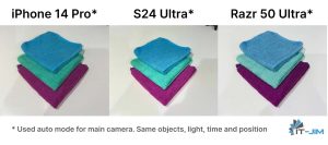
Different color reproduction across devices based on the photos showcasing three towels

The root cause of color inconsistency lies in the hardware and software processing. Modern smartphone cameras rely on a series of automated adjustments known collectively as the 3A pipeline.

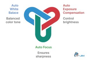
First, Auto-Focus analyzes contrast in the scene to lock onto the sharpest subject. Then Auto-Exposure measures overall brightness and adjusts shutter speed and aperture. Finally, Auto-White-Balance estimates the scene’s color temperature, whether warm incandescent light or cool daylight, and applies corrective tint so that whites appear neutral.

All of these decisions draw on built-in light meters and computer vision (CV) before the sensor data proceeds to multi-frame fusion and further enhancement.

3A color pipelines that include balanced color tone, brightness control, and sharpness

A mobile application that delivers a stable color signal regardless of lighting conditions can become a competitive advantage for both end users and enterprise customers.

Context of Existing Solutions

Let’s examine how modern smartphones process images “under the hood” and why this affects color consistency across devices.

The simplified flow diagram below illustrates the overall pipeline.

High-level diagram showing the color consistency in a camera device

Smartphone cameras begin by capturing light through a grid of red, green, and blue filters and then reconstruct a full-color image by filling in the missing data.

They automatically adjust focus, exposure, and white balance before blending multiple exposures and reducing noise to produce a clear, well-lit photo. While these steps make images look good, each phone’s unique processing can shift colors so that the same scene may appear differently on different devices.

Some newer smartphones even replace the entire sequence with a single deep-learning-based image-signal-processing model (DeepISP). One common workaround uses physical color targets, such as the X-Rite ColorChecker, or laboratory-grade spectrophotometers, which provide reference spectral data but are bulky and expensive.

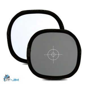
Another approach is to calibrate the camera using a white and/or gray card of known reflectance. By using the card as a reference, photographers can ensure that colors will accurately reproduce and that the image is correctly exposed.

However, this method requires manual setup and cannot guarantee perfect results, especially when the device is in motion or the lighting is changed.

Grey reference reflector for camera calibration

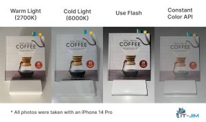
In iOS 18, Apple introduced the Constant Color API framework, which activates a dedicated “studio” flash mode to capture images with a neutral white balance regardless of ambient light sources.

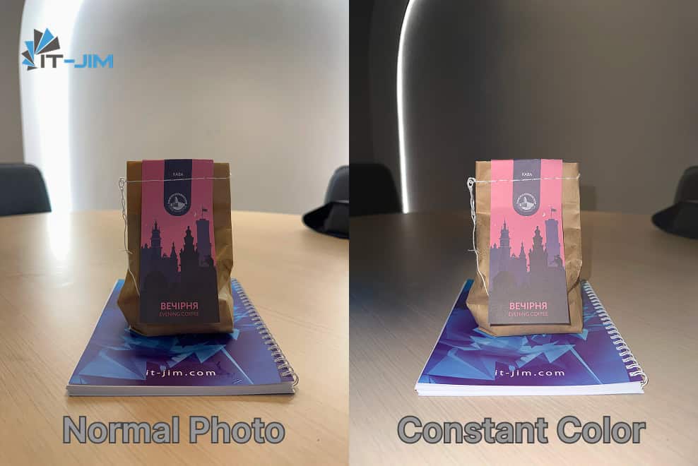
Four images of the same coffee package by using different camera settings

Conventional pipelines such as 3A, HDR fusion, denoising, and tone mapping are unsuitable for exact color measurement, while producing visually pleasing results for general viewers. Physical targets and spectre-processing devices remain impractical for mobile applications.

The Constant Color API and similar “studio-lighting” approaches combine ease of use with accuracy, delivering both stable color captures and per-pixel confidence data. These outputs enable advanced features such as extracting the exact color of a selected region of interest.

Taming the Constant Color API

To obtain a “studio”-quality image free from color distortion, we selected the Constant Color API in AVCapturePhotoOutput, available from iOS 18 onward.

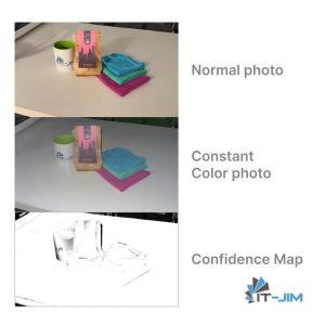
In this mode, the system fires the device’s built-in flash at a fixed spectrum and locks the white balance regardless of ambient lighting. In addition to the image itself, the API returns a confidence map that enables assessment of measurement accuracy within a selected region.

Samples of normal photo, constant color photo, and confidence map

It is important to note certain device limitations. The mode is supported only on hardware with a sufficiently powerful flash (iPhone 14 and newer). It disables manual exposure control and requires RAW capture to be turned off. In very low‐light conditions without enough reflected flash, the quality of the confidence map may degrade.

To leverage the Constant Color API, a specific AVCaptureSession configuration is required:


func setupCaptureSession() {
    defer { captureSession.commitConfiguration() }

    // Some default setup for AVCaptureSession
    captureSession.beginConfiguration()  
    captureSession.sessionPreset = .photo
    // setup AVCaptureDeviceInput, AVCaptureDeviceOutput, 
    // AVCaptureDevice, depth data and quality

    // Special option for Constant Color API

    // A BOOL value specifying whether constant color capture is supported 
    // This property returns YES if the session's current configuration allows 
    // photos to be captured with constant color. When switching cameras 
    // or formats this property may change
    photoDataOutput.isConstantColorEnabled = photoDataOutput.isConstantColorSupported
}

In the AVCapturePhotoCaptureDelegate, the AVCapturePhoto object now exposes additional properties:

  • constantColorConfidenceMap – a pixel buffer with the same aspect ratio as the constant color photo, where each pixel value (unsigned 8-bit integer) indicates how fully the constant color effect has been achieved in the corresponding region of the constant color photo – 255 means full confidence, 0 means zero confidence.
  • constantColorCenterWeightedMeanConfidenceLevel – score summarizing the overall confidence level of a constant color photo.

func photoOutput(
    _ output: AVCapturePhotoOutput,
    didFinishProcessingPhoto photo: AVCapturePhoto,
    error: Error?
) {
    if photo.isConstantColorFallbackPhoto {
        normalPhotoImage = // convert AVCapturePhoto to UIImage and save
        // Return for waiting next photo with Constant Color data
        return
    }

    // Save Constant Color image photo
    constantColorPhotoImage = // convert AVCapturePhoto to UIImage

    // Get Confidence Map pixel buffer
    let photoConfidenceMap: CVPixelBuffer = photo.constantColorConfidenceMap

    // Save Confidence Map image photo
    confidenceMapImage = // convert CVPixelBuffer to UIImage


    // Set parameters of ROI
    let roiSize: Int = 30    // in pixels
    var roiColor: UIColor? = nil
    var roiConfidence: Float? = nil


    // Get color of ROI
    guard let cgImage = constantColorPhotoImage.cgImage else { return }

    // Init rect for ROI (zone in center of photo)
    let rect = CGRect(
        x: (cgImage.width - roiSize) / 2,
        y: (cgImage.height - roiSize) / 2,
        width:  roiSize,
        height: roiSize
    )

    // averageColor is our special UIImage extension next
    roiColor = // calculate color from constantColorPhotoImage by rect
        
    // Calculate confidence for ROI
    if let avgGray = confidenceMapImage?.averageColor(rect: rect) {
        var white: CGFloat = 0
        var alpha: CGFloat = 0
        avgGray.getWhite(&white, alpha: &alpha)
        roiConfidence = Float(white)        
    }

    // Return feedback for sharing info about photos and colors
}

It is important to recognize that the chosen region of interest (ROI) size critically affects color accuracy.

Through experimentation, we discovered that regions smaller than 20×20 pixels yield technically correct readings but tend toward muted, pastel tones. Besides, regions larger than 50×50 pixels preserve saturation more faithfully, yet the extracted color often blends into a grayer spectrum, losing its special hue.

To compute the region’s average color, we implemented a UIImage extension that accepts a CGRect parameter, applies a Core Image filter to the specified area, and returns the resulting UIColor.


func averageColor(rect: CGRect) -> UIColor? {
    let ciAvgFilterName = "CIAreaAverage"
    
    // Crop original CGImage to specified rect
    guard let cgImage = cgImage?.cropping(to: rect) else {
        return nil
    }
    // Create CIImage from cropped CGImage for usage CIFilter
    let ciImage = CIImage(cgImage: cgImage)
    
    // Init avg filter by name
    guard let filter = CIFilter(name: ciAvgFilterName) else {
        return nil
    }
    
    // Set the input image for the filter
    filter.setValue(ciImage, forKey: kCIInputImageKey)
    
    // Obtain the filter output, which is a 1×1 CIImage representing average color
    guard let output = filter.outputImage else {
        return nil
    }
    
    // Prepare buffer to hold RGBA8 pixel data
    var bitmap = [UInt8](repeating: 0, count: 4)
    
    // Render the CIImage into the buffer to extract pixel bytes
    CIContext().render(
        output,
        toBitmap: &bitmap,
        rowBytes: 4,
        bounds: CGRect(x: 0, y: 0, width: 1, height: 1),
        format: .RGBA8,
        colorSpace: CGColorSpaceCreateDeviceRGB()
    )
    
    // Convert RGBA8 bytes into UIColor normalized to [ 0, 1 ] range
    return UIColor(
        red:   CGFloat(bitmap[0]) / 255,
        green: CGFloat(bitmap[1]) / 255,
        blue:  CGFloat(bitmap[2]) / 255,
        alpha: 1
    )
}

Project Demo Video and Images

The specialized configuration phase is complete, and now we move on to the demo. To showcase the logic we have implemented, we will recreate a user interface composed of a Main View featuring a Capture Button and a separate Preview View.

In the Preview View, we will present four interactive cards: Color, Confidence Map, Constant Photo, and Normal Photo. On the Color card, we will add functionality to find the closest matching RAL palette color based on the captured RGB values.


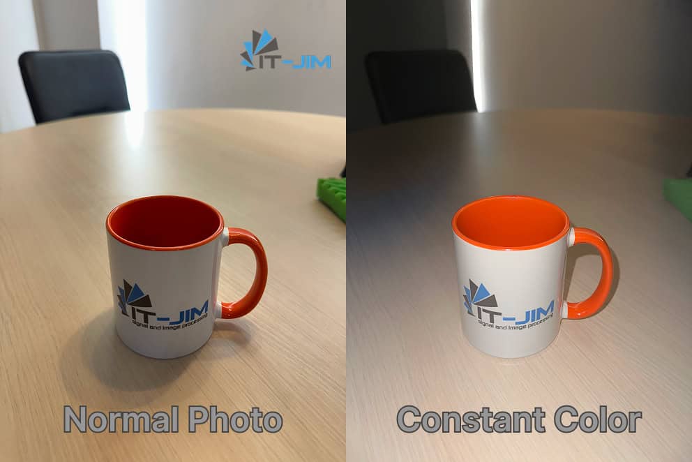
Interactive demo example comparing a normal photo and a constant photo of a cup with the It-Jim logo


Interactive demo example comparing a normal photo and a constant photo of a coffee package


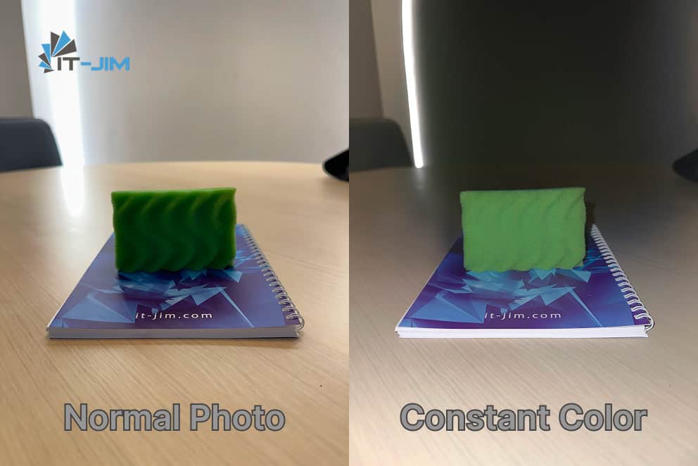
Interactive demo example comparing a normal photo and a constant photo of a washing sponge

Let’s Finalize About the Constant Color API

Accurate color measurement in the field remains a nontrivial challenge: the spectral characteristics of light sources, surface properties, and the camera’s internal processing all introduce their distortions.

Our implementation based on the Constant Color API shows that on modern devices, by using a controlled “studio” flash and a per-pixel confidence map, one can closely approximate the true hue: the resulting images render object and surface colors far more naturally, narrowing the gap between digital capture and human perception under neutral (diffuse) lighting.

It must be remembered again that this method does not guarantee 100 % correlation with the optical spectrum. In the real world, factors such as material, surface roughness, ambient light, and camera angle still require additional compensation. However, access to pixel-level confidence and the ability to programmatically filter out “weak” regions open new horizons for mobile color-measurement solutions.

Looking ahead, integration of machine-learning models for advanced spectral correction promises further gains – each year, these networks become more capable of inferring true colors despite variable lighting.

Yet even today, the Constant Color API represents a powerful tool for achieving far more natural color reproduction than previously available methods.

How would you apply this technology? Can our current handheld devices truly see and convey pure color to us?

Computer Vision Technology Costs: Key Factors & Use Cases

Computer Vision Cost: Understand Your Budget to Build Powerful Vision AI Solutions

How much does computer vision technology cost?

To make a long story short, the rough cost of the basic AI vision software or pilot project starts at $30,000. The more advanced computer vision solution costs around $100,000 or higher.

The overall cost of the computer vision project depends on its complexity, data acquisition processes, integration requirements, compliance and security matters, as well as specifications of hardware and software components. Additionally, consider price variations concerning industry-specific use cases, annual maintenance costs, and the selected team of CV experts working on the project. For accurate budgeting, it is essential to evaluate all these factors.

Thus, many unknown aspects make it challenging to calculate the precise development costs of R&D projects. This aspect leads to unpredictability and imprecision in estimates, particularly in the early stages.

In this comprehensive guide, our team will examine the cost of computer vision software and help you plan your investment accordingly. You’ll discover:

  • Key factors influencing the final cost of a computer vision project.
  • Understand if computer vision is indeed expensive.
  • Specifics of software and hardware costs involved.
  • AI vision pricing options on the selected infrastructure setup.
  • Computer vision development cost breakdown for each project phase.
  • Use cases and cost of computer vision across industries.
  • Strategies to optimize your computer vision model costs.

Let’s start by exploring the specifics of computer vision technology.

Is Computer Vision Expensive to Implement?

The global AI vision market is estimated to be worth $15.85 billion and projected to reach $108.99 billion by 2033, representing a 24.1% annual growth rate.

Such an incredible demand for innovations is also supported by government initiatives that promote digital transformation and sustainability. As a result, entrepreneurs in various fields utilize modern technologies, including deep learning models and computer vision, to enhance their operations.

AI vision market size and growth forecast 2023-2033

The primary goal of the technology is efficiency, as it converts raw footage into informed business decisions. At the same time, economic feasibility plays a critical role; if the implementation costs of computer vision are too high, the business case falls apart.


“CV is expensive. – Yes, if you’re solving the wrong problem or building the wrong solution. But when designed right, it replaces hours of manual work, reduces human error, and delivers long-term savings”.

Ievgen Gorovyi, PhD in Computer Vision & Founder at It-Jim


Thus, the investment in AI vision projects can be substantial, but it offers significant benefits. Emerging AI technology and computer vision aid in process automation, accuracy improvement, cost optimization, and enhanced efficiency.

Computer vision is a relatively new AI technology that needs a skilled pool of talent. It may be challenging to find genuine professionals with relevant expertise. Top-notch technicians, AI consultants, and solution architects are in high demand, and even a small team can be costly, becoming the project’s most significant expense.

Other challenges may lie in lighting, motion, hardware limitations, deployment environments, computational burden, and, most importantly, user experience and business optimization. If one piece is missed, the business ROI crumbles. As a result, even a highly experienced team needs to invest significant effort and time to turn a computer vision software idea into reality.

To conclude, computer vision algorithms are costly and require a significant amount of technical expertise to implement effectively. On the other hand, it doesn’t mean that computer vision implementation is out of reach for smaller businesses; it simply means that companies must be cautious when deciding how to deploy computer vision technology.


Here’s my take: the biggest cost in computer vision isn’t the tech. It’s the gap between assumptions and reality.”

Ievgen Gorovyi, PhD in Computer Vision & Founder at It-Jim


Save time and connect with our experts by sharing your computer vision software idea. 

Factors Influencing Computer Vision Costs

When estimating the cost of a computer vision project, you must consider several key aspects. Let’s outline each of them one by one.

1. Project Scope & Complexity

The scope of the AI vision project directly influences cost. The solution may include advanced functionalities such as real-time processing, image recognition, object detection, multi-camera support, 3D modeling, and similar capabilities.

These computer vision tasks require a higher number of necessary resources (hardware and technical expertise) compared to simpler functions. As a result, this aspect drives the need to incorporate machine learning models and establish a high-performance computing infrastructure.

Additionally, software complexity isn’t just about algorithms. It encompasses the overall scale, interdependencies, and advanced technologies required to develop practical computer vision applications.

For example, basic object detection projects can range from $10,000 to $30,000, while custom model development can start at $50,000 and increase in cost depending on complexity.

Real-time video analysis projects typically cost between $40,000 and $100,000, while advanced 3D computer vision solutions can exceed $100,000. These figures clearly indicate that the price of computer vision projects varies significantly.

2. Data Amount & Quality

Gathering the necessary data helps train AI vision software to complete tasks with higher accuracy. The proper amount and quality of data are critical factors influencing the success of machine and deep learning models.

Obtaining high-quality, annotated data from a large dataset requires time and resources. You can either use applicable data from in-house sources (e.g., video footage, images) or public databases, or purchase it from a third-party provider.

The price of computer vision can vary depending on the chosen data acquisition method and the required quality. High-quality data annotation costs more, but it leads to better model accuracy and performance. Achieving higher accuracy often requires more complex algorithms and increased development costs and time.

3. Hardware Investments

The price of hardware components can also become a significant factor in the overall project cost, particularly for those with an edge-based approach.

It is necessary to invest a substantial amount of money in high-quality cameras, processing capacities, and other equipment that support the project objectives to capture and process visuals.
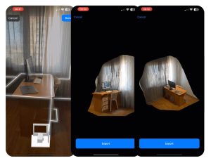
Some typical hardware components of vision AI systems include:

  • Industrial cameras or other types of sensors.
  • Graphics Processing Units (GPUs) for parallel image processing and network training. Access to sufficient GPU resources is essential for running deep learning models efficiently, especially when processing images or video frames on remote data center servers.
  • Edge devices for real-time processing, such as mobile devices, cameras, robots, or embedded IoT systems.
  • High-performance CPUs and RAM for complex tasks of image preprocessing and data augmentation. Powerful processors are essential for handling resource-intensive image processing tasks, directly impacting the efficiency and cost-effectiveness of computer vision.

It is crucial to capture and handle data accurately, with high security in mind. This element is essential, for instance, in healthcare projects, where privacy and data concerns are vital.

Additionally, factors such as environmental conditions and camera placement may impact the total investment in hardware. Sufficient physical space is necessary to accommodate hardware and ensure proper integration, especially in cluttered environments.

Regarding investment in camera equipment for computer vision projects, the price ranges from just $30 to $3,500 per unit. The cost varies depending on resolution, transfer speed capabilities, and other features.

Camera type Price range Features
Basic $30 – $200 Standard resolution, basic transfer speeds
Professional $200 – $1,500 High-resolution, advanced features
Enterprise $1,500 – $3,500 Premium specs, industrial grade

4. Software Frameworks & Tools 

Software costs in computer vision projects can differ substantially, especially when comparing proprietary and open-source options. The general advice is to look beyond the initial subscription or licensing fees. Take into consideration ongoing costs associated with hosting, software updates, and any necessary customization or integration.

Open-source tools such as TensorFlow, PyTorch, and OpenCV provide a robust and adaptable foundation for developing custom computer vision software. Integrating various machine learning platforms within a project can significantly impact system complexity, maintenance, and overall implementation costs.

These tools give access to source code and community resources, which are ideal for teams that need customization and budget management. However, developing and maintaining custom computer vision software can be resource-intensive, requiring significant processing power and specialized expertise.

In comparison, off-the-shelf AI vision solutions, such as MATLAB, offer better support and easy-to-use interfaces. Yet, these services come together with substantial licensing fees, extra costs for support, and unsuitable functionality.

Thus, many companies opt to develop custom AI vision solutions, as they offer improved accuracy and performance.


“Off-the-shelf models might get your 60-70% accuracy. Sounds fine until you realize that in production, 70% of the time, it fails. When a business problem is specific, your solution has to be too”.
Ievgen Gorovyi, PhD in Computer Vision & Founder at It-Jim


5. Integrations with Internal Systems

Integrating with existing systems or databases increases the total cost of building computer vision solutions. For seamless communication, we need custom API development, data mapping, and thorough testing to ensure that the AI vision service functions correctly.
In addition, architectural design choices and infrastructure setups have a significant impact on integration and costs. Complex architecture can raise costs. This is particularly true when adding advanced features or ensuring the system integrates smoothly with existing workflows. We will elaborate on the specifics of infrastructure costs further in detail.

Using standard interfaces and protocols can facilitate seamless integration. Organizations should be cautious of technology lock-ins when utilizing computer vision systems. Relying on off-the-shelf solutions can limit flexibility and make future upgrades more challenging.

6. Personnel Expertise & Team Location

Top computer vision engineers earn high salaries since they offer a top level of expertise and knowledge. This adds to the costs of computer vision projects, especially for advanced solutions.

Additionally, the costs of implementing computer vision vary depending on the selected development model. Companies can choose from an in-house model, hiring an individual AI consultant, or working with a remote team (IT outsourcing). 

In-house development often requires additional equipment and increases staffing costs. Additionally, the location of an AI and CV software development company influences project pricing, as labor salaries can vary significantly across different regions. Hourly rates of CV professionals on the local market can be 30-50% higher than addressing a team of CV specialists from Eastern Europe, for example.

Therefore, delegating computer vision software development to a remote team of professionals, such as It-Jim, is a wise decision. This way, you save on your budget and receive top-quality expertise. 

Our team has developed various business solutions that utilize computer vision technology for object detection, productivity monitoring, visual search recommendations, and more. 

Our team has developed various business solutions utilizing computer vision technology for object detection, productivity monitoring, visual search recommendation, and more. 

Reach out to our CV experts and discuss the project from both technical and business perspectives to ensure a high ROI in your business case.

Infrastructure Computer Vision Costs: Cloud vs. Edge Computing

An illustration depicting various key factors influencing computer vision price, including technology and hardware costs

Infrastructure choices, including the need for cloud storage and processing resources, primarily drive software development costs. Choosing between cloud-based and edge computing has implications for project cost, efficiency, and latency.

Many overlook the architectural design when estimating the costs of computer vision.

Computer Vision Cost: Cloud-Based Solutions

Cloud-based solutions utilize popular systems such as AWS Rekognition, Azure Cognitive Services, or Google Cloud AI Vision. These services connect via APIs that send every image or camera frame (data) to a cloud server for processing. The API response usually includes detected classes or OCR data. These details are key for grasping API performance and cost.

These cloud services have flexible pricing. They charge based on units, detection, labels, or frames per second (FPS). For most CV projects, you need a mix of these services to cover all AI vision tasks and boost output accuracy. A plate recognition system needs three services: car detection, plate number identification, and plate reading. Thus, estimating the cost of cloud-based computer vision with precision may be challenging.

As a result, a cloud-based method offers flexibility and a lower initial investment. These solutions offer free trials for small PoC projects with low-volume testing. However, the price can rise significantly due to latency issues, higher processing volumes, or scalability needs. There is also a risk of bottlenecks. These can raise costs since the system requires a constant internet connection to work well.

Computer Vision Price: Edge Solutions 

Edge computing enables rapid data processing, removing the need for data transmission to a central server. The system operates on physical computers and servers with direct network connections. This decentralized method is very scalable. You can add or remove edge endpoints without affecting the others. Edge AI is crucial for real-time processing and privacy protection, and it works well in settings such as smart factories.

This method requires a larger upfront investment in hardware, such as local processors or AI accelerators. Despite high investment, edge computing can cut costs over time and improve efficiency. It processes data locally, which is especially helpful for large projects.

Here’s a comparison table showing the main differences between cloud-based and edge-based AI:

Factor Cloud-Based AI Vision Edge-Based AI Vision
Latency Higher latency due to network transmission Low latency with real-time processing on-device
Connectivity Requires a stable internet connection Works offline or with intermittent connectivity
Processing Location Data is sent to the cloud for processing Processing occurs locally on the edge device
Bandwidth Usage High, as raw or semi-processed data is transmitted Low, since data is processed and filtered locally
Hardware Requirements Lightweight devices: heavy lifting is done in the cloud Requires powerful edge devices (e.g., GPUs, TPUs)
Scalability Easily scalable; resources can be added in the cloud Scaling may require deploying and managing more edge devices
Security & Privacy More risk; data is transmitted and stored remotely Improved privacy; data remains local
Maintenance & Updates Easier to update centrally More effort is needed to update distributed edge devices
Cost Model Ongoing costs for cloud services and data transfer Higher upfront hardware cost but lower long-term cloud fees
Use Cases Ideal for batch processing, analytics, or centralized monitoring Best for time-sensitive tasks like real-time detection, control

In conclusion, a good infrastructure choice lies somewhere in between, and many adopt a hybrid approach that balances cost efficiency and system performance. The optimal option depends on project size, performance requirements, and long-term scalability needs.

Computer Vision Cost Breakdown per Project Phase

Dividing software development into phases helps manage the project budget efficiently. You can break down the cost of a computer vision project into the following stages:

  • Planning the project.
  • Preparing the data.
  • Developing the computer vision model.
  • Implementing and deploying the system.
  • Testing and quality assurance.
  • Maintaining and updating the solution.

In this part, we will elaborate on these steps of developing an AI vision solution in greater detail.

1. Project Planning and Scope Definition

Clear goals and careful planning help companies establish a strong foundation for their software development projects. This stage typically accounts for approximately 10% to 15% of the total cost of the computer vision project. It may produce the following deliverables:

  • Defined project goals and success metrics.
  • Defined project functionality and scope.
  • Established agreements among stakeholders.
  • Allocated budget and personnel.
  • Estimated a rough project cost and timeline.
  • Set realistic milestones and deadlines.
  • Ensured adequate data availability for the CV model.

Early project discussions with clients are crucial for gathering information and requirements, establishing a clear roadmap, and preventing scope changes. With clear objectives, you can boost project success and get the expected results. The approach helps manage the development costs of a computer vision solution and optimizes the budget.


Ironically, skipping early scoping is what usually delays the project later. We’ve learned that the best way to speed things up is to slow down just enough at the start.

Ievgen Gorovyi, PhD in Computer Vision & Founder at It-Jim


2. Data Preparation & Model Creation

For the project to succeed, it is necessary to have sufficient, high-quality data (e.g., relevant images, video materials) for the system to analyze and learn from. Depending on the problem you want to solve, you can utilize public datasets, synthetic data, or custom image capturing.

Once there is enough data pool, the next step is to label it correctly (e.g., segmentation masks, classification tags, or bounding boxes). Proper labeling ensures that the computer vision model knows what to search and what results to provide, thus directly influencing the system’s accuracy and performance. The choice of AI model architecture also plays a crucial role, as it can significantly affect both the accuracy and cost of the computer vision system.

Thus, data acquisition, annotation, and computational resources for model training can vary widely depending on the specific use case, ranging from 20% to 50% of the budget.

3. Project Implementation & Deployment

The development phase typically incurs the highest costs of a computer vision project, accounting for more than 50% of the total budget. This step corresponds to the need for engineering expertise, system integrations, and security matters.

Agile development approaches (e.g., Scrum and Kanban) help minimize costs by aligning implementation with project needs. Focusing on critical functionality can streamline timelines and prevent budget overruns.

Architectural design choices and infrastructure setups have a significant impact on the integration process and associated costs for computer vision. It is vital to deliver system compatibility with the existing workflow and ensure seamless integration of CV models into production. At this stage, MLOps becomes crucial. It aids in version control, CI/CD, performance monitoring, and scaling computer vision models for deployment in real-world settings.

Also, security is vital for protecting sensitive image data and intellectual property. If you need this functionality, be aware that it can be costly and requires investment in infrastructure hardening, data encryption, and continuous monitoring.


“Accurate cost estimation starts with understanding the unique data and infrastructure challenges of each business. Missing these details can lead to underestimations of 70%.”

Ievgen Gorovyi, PhD in Computer Vision & Founder at It-Jim


4. Testing & Quality Assurance

The testing and QA stage is crucial to ensuring the reliability and accuracy of AI vision systems. Rigorous testing methodologies and tools are used to identify issues early and provide scope for improvement.

Computer vision costs can increase due to custom API developments, data mapping, and extensive testing when integrating with existing systems. It is a wise strategy to initiate QA in the early development stages, as it enables refinements based on user feedback, ensuring a high level of accuracy and performance.

5. Ongoing Support & Maintenance

Maintaining the latest functionality and high security level of computer vision solutions can be achieved through regular updates and improvements. These updates typically incur an annual cost of approximately 20% of the original computer vision project cost

Ongoing monitoring and technical support guarantee optimal system performance. Technical support helps resolve issues quickly, ensuring the system operates smoothly and efficiently. Monitoring helps identify problems early and prevent significant downtime, ensuring steady performance.

The table below provides a rough cost allocation for each project phase.

Project Stage Typical Cost Share (in %) Key Considerations
Project Planning  10% – 15% Define project scope, functionality, integrations, and infrastructure setup
Data Preparation & Model Creation  20% – 50% Data collection, cleaning, and annotation.

Algorithm selection, training, and validation.

Implementation & Deployment 40% – 60% System integration and deployment.
QA & Testing 15% – 20% System testing, scope for improvements, and quality assurance
Ongoing Support & Maintenance (annually)  10% – 20% Ongoing support, updates, and scalability enhancements.

Estimated Timeline & Cost of a Computer Vision Project

As mentioned, the key drivers of computer vision cost include software complexity, industry requirements, integrations, data testing and annotation processes, deployment method, and the selected team of AI developers.

Taking all these cost factors into account, the total budget for developing a solid computer vision solution is within the $100,000 to $350,000. But if you want to test the technology or implement a system with prioritized functionality, the cost starts at $60,000 for an MVP project. 

The table below provides rough estimates based on the type of computer vision project.

Project Complexity Development Cost Development Timeline Specifications
Pilot, Simple Project $10,000+ 1-2+ months PoC project to test the hypothesis
Basic AI Vision Software $30,000+ 2-3+ months MVP project with basic features (e.g., OCR, simple classification)
Moderate CV-based Project $60,000+ 3-5+ months mid-level complexity

1-2 complex features (e.g., object detection)

Complex Visio AI 

Software

$100,000+ 6-12+ months advanced functionality (e.g., custom ML models, real-time tracking), enterprise-level

The basic computer vision solutions cost around $30,000 and last 2-3 months. Designing and building solutions of medium complexity typically begins at $60,000, with a 3-to 5-month timeline. The pricing for advanced systems with increased precision can exceed $100,000 and last for more than 6 months. Logically, the more complex the system is, the longer it takes to implement.

Important Note on Proof of Concept

Proof of concept (PoC) is a strategic step and one of the best ways to start with vision AI projects. Since there is a significant number of unknown elements, through pilot testing, it is possible to elaborate on the project’s feasibility and refine the solution using real-world feedback.

A PoC project typically takes 1 to 3 months and costs only 10-20% of the computer vision budget. Here are the benefits you can expect:

  • Identify potential challenges before the project launches.
  • Understand methods to overcome burdens or limitations encountered.
  • Update the project scope based on feedback from real-world settings.
  • Validate performance standards and system metrics.
  • Reduce risks associated with full-scale vision AI implementation.

Want to estimate the cost of implementing your custom vision AI idea?

Contact our experts, and they can help analyze your project requirements and outline an initial budget. 

Computer Vision Price Across Industries

According to the recent McKinsey report, organizations are increasingly utilizing AI and computer vision technology across multiple business functions, including product and service development, service operations, and software engineering.

Computer vision utilization across industries

Computer vision enables organizations to automate tasks, reduce costs, enhance accuracy, and increase productivity. For instance, artificial intelligence and computer vision in healthcare are utilized to enhance diagnosis and reduce operational expenses.

New capabilities enabled by computer vision technology allow organizations to develop innovative solutions for operational challenges. The ROI of computer vision can differ by industry, use case, and implementation.

Many are already seeing impressive results with the following functions:

  • Manufacturing & Industrials: visual inspection, predictive maintenance, defect detection, quality control, safety, and workforce monitoring.
  • Logistics & Warehousing: package tracking, inventory detection, storage optimization, goods counting, object detection, automation.
  • Healthcare: medical imaging, segmentation, diagnostics support, patient monitoring.
  • Sports & Fitness: pose estimation, real-time movement tracking, athlete analysis.
  • Retail & E-commerce: shelf monitoring, customer behavior analysis,  product recognition, visual search, optical character recognition (OCR), inventory management.
  • Real Estate & Construction: 2D and 3D modeling, layout recognition, property measurements, virtual tours.

Computer vision costs vary across industries due to differences in data complexity, infrastructure requirements, system integration challenges, and regulatory demands.

Key cost drivers include the need for high-precision models, real-time processing, specialized hardware, and compliance with sector-specific standards such as HIPAA in healthcare or GDPR in retail. The scale of deployment and the solution’s integration with current systems also greatly affect the total investment.


At It-Jim, we don’t just build things that operate; instead, we create things that continue to work even when reality gets messy.

We deliver tailored, cost-effective CV solutions across various industries, including manufacturing, sports, healthcare, and retail. If you’re building a new AI product or struggling to get an existing one to perform, let’s talk.

How to Cut Down Computer Vision Software Development Costs

Employing cost-effective strategies maximizes the return on investment in computer vision projects. Focusing on key features, utilizing open-source tools, and rolling out updates in phases can help reduce costs.  

Here’s a helpful list of tips to save money on your next computer vision project:

Advice 1: Prioritize the functionality

To effectively manage and optimize your development budget, elaborate on the essential and secondary functionalities of your solution. Such prioritization helps launch a project within a defined timeline and start testing it in a real-world setting more quickly.

Advice 2: Plan the data collection process

The issue with the data lies in the quality of relevant use cases and correct data labeling so that the system achieves a high accuracy level. Therefore, ensure that you delegate this process to a reputable team of professionals, such as It-Jim.

Advice 3: Consult with experts before investing in hardware or software

Before purchasing hardware or other sensors to collect and process data, you’d better consult with experienced CV professionals like It-Jim to avoid pitfalls. Even high-quality cameras and hardware components may not be suitable for a project’s needs, and investing in them may result in a waste of money.

Choose the software to be used in the CV project carefully. Consider your team’s tech skills and the project’s long-term maintenance needs. Open-source tools can save money and provide flexibility. However, they may require additional resources for management and updates.

Advice 4: Leverage open-source technologies

Using open-source frameworks for computer vision projects provides flexibility, cost-effectiveness, and access to extensive community resources. Open-source tools can increase development speed and reduce resource needs, thereby enhancing efficiency.

Proprietary software often incurs licensing fees and limits customization options, leading to higher ongoing costs. Thus, leveraging open-source tools can lead to significant cost savings.

Advice 5: Follow a step-by-step implementation

Breaking down computer vision projects into manageable stages makes the process less overwhelming and more flexible. The phased implementation enables organizations to allocate their budgets more effectively and avoid significant upfront investments.

This method facilitates continuous learning, enabling businesses to adapt their strategies based on early-stage results and feedback. The gradual approach not only minimizes risks but also enhances overall project efficiency and effectiveness.

Advice 6: Start with PoC

Proof-of-concept projects help businesses improve their computer vision solutions. Many unknown factors exist in projects that use AI and computer vision technology. Pilot projects help refine solutions by using real-world feedback and data. This method reduces risks and enhances the system before full deployment.

Advice 7: Choose an IT outsourcing model

If you’re on a tight budget, consider remote or outsourced development as an option to lower your computer vision costs. Reach out to experts in Eastern Europe, who possess a high level of education and technical experience, with rates ranging from $100 to $150 per hour, compared to $300 in the USA.

Conclusion on Computer Vision Cost Estimation

Process of estimating the computer vision project cost

Measuring the return on investment (ROI) for computer vision projects can be tough.

In terms of immediate benefits, you can expect lower operational costs from automation, improved accuracy in quality control, and faster detection of defects or errors. Regarding the longer-term benefits, computer vision technology may lead to enhanced customer satisfaction, a stronger brand reputation, and access to new revenue streams with improved capabilities.

Thus, starting a computer vision project can be challenging, but it can also transform your business for the better. Success needs more than just technical skills. You also need clear goals, good data, and a solid plan from the start.

To sum things up, the key ideas derived from this extensive evaluation of computer vision pricing are as follows:

  1. Understanding key cost drivers, including project complexity, data collection, and integration needs, is essential for effective budget planning.
  2. The main cost drivers of a computer vision project include the complexity, industry-specific requirements, data acquisition, annotation, training, integrations, software and hardware specifications, and potentially other unknown factors. 
  3. Step-by-step implementation, prioritization of essential features, and leveraging open-source tools are proven strategies to minimize computer vision costs.
  4. The costs associated with computer vision vary significantly across different industries, depending on the specific application requirements.
  5. Real-world examples demonstrate the practical benefits and cost savings of computer vision technology. 
  6. Starting a project with proof of concept is a wise strategy to ensure feasibility and project effectiveness.

Why Choose IT-Jim for AI & Computer Vision Development?

Partnering with IT-Jim for AI and computer vision development offers several competitive advantages, namely:

  • Multidisciplinary team with 10+ Ph.D. holders across multiple scientific domains (Physics, Mathematics, Biophysics).
  • R&D company with a portfolio of 100+ successful projects in computer vision, image and signal processing, machine and deep learning.
  • Offers intellectual processing of visual information for advanced tech applications.
  • Delivery of tailored, cost-effective solutions that align with your business needs.

According to Clutch and our client’s feedback, “It-Jim provides competitive pricing and good value for cost, as highlighted by clients who appreciated their budget fit and quality deliverables. Project investments ranged from $10,000 to $100,000, with a strong emphasis on cost efficiency and effective resource management.”

To finalize, by leveraging the expertise of It-Jim, businesses can optimize their costs for computer vision projects and achieve their desired outcomes.

When you’re ready to move forward, we can help bring your vision to life. We ensure your computer vision projects deliver maximum value and long-term ROI.

Extended Reality Project: Code Samples & Demos

Extended Reality – XR: A Gateway to Spatial Interfaces

The Augmented Reality (AR), Mixed Reality (MR), and Virtual Reality (XR) markets continue to evolve and grow rapidly. Once the stuff of science fiction, it is now part of the future reality.

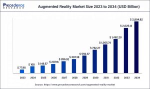
Precedence Research predicts rapid growth in the AR and VR market over the next decade, as illustrated in the graph below.

Graph representing size of AR&VR market 2025-2034

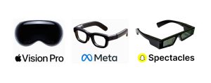
Users are increasingly interested in portable XR devices, driven by the emergence of spatial devices such as Apple Vision Pro and Meta Glasses. These platforms have normalized gesture-based interaction, especially the pinch gesture, as a natural way to control virtual content.

Images of Apple Vision Pro and Meta Glasses

At It-Jim, we’re inspired by the vision of a world where physical and virtual environments are seamlessly blended, and interaction with them is intuitive and unified.

In this small project, we aimed to determine if XR-type gestures can be achieved on a regular iPhone before XR glasses become widely adopted.

A key stage of the project involved technical research, where the task was to evaluate the feasibility of implementing such a system using only built-in iOS tools.

While third-party solutions were considered, deeper analysis revealed that all the necessary mechanisms are already available natively through Apple’s Vision Framework, ARKit, and RealityKit.

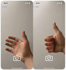
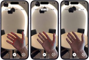
We already have experience with and existing solutions that utilize Hand Pose Detection, including the demo featured in this article. input in admin panel/ example to use:

Example of hand pose detection using iPhone camera

Let’s define the key aspects of our task: tracking stability, recognition accuracy, minimal latency during video stream processing, and the ability to integrate this data into the AR scene.

Chosen Approach for Extended Reality Project Implementation

Based on the results of our research, we formulated the hypothesis that building a gesture-first AR application is entirely feasible, even without the use of large-scale ML models or external SDKs.

Instead of complex or multilayered solutions, it is sufficient to correctly combine the Vision Framework as a source of hand motion data with ARKit as the tool for rendering and handling the spatial scene.

This combination forms the foundation of the application. We defined the working scheme of future services and their communication flow.

Responsibilities are divided into dedicated services:

  • AR-related operations service: handles ARKit operations, manages the 3D scene, and provides ARFrame output at a defined FPS.
  • Hand tracking within provided frames: processes ARFrame data to analyze finger positions and send back control signals.

For gesture control, we focused on gestures that are both easy to track and naturally understood by users.

Communication Flow in the Extended Reality Project

During the initialization phase, the following sequence takes place.

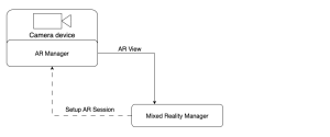
First, a session is created (once), and the corresponding ARView is obtained to render the scene to the user.

Diagram showing the initial AR session setup

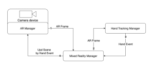
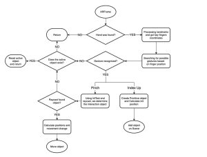
A continuous processing loop begins, where the AR Manager sends AR Frame data to the MixedRealityManager.

From there, it is forwarded to the Hand Tracking Manager for analysis. The results are then returned to the MixedRealityManager, which determines the appropriate changes to apply within the AR session. 

Diagram showcasing AR session with MixedRealityManager

With the idea, hypothesis, and signal flow defined, we are ready to begin building the actual implementation.

The Art of Control AR Scene

To manage the AR scene within the application, we defined a dedicated service that implements the ARManager protocol. Its primary purpose is to provide the MixedRealityManager with abstract access to the required ARKit capabilities without coupling it to the framework’s internal details or any additional nested logic.


protocol ARManager {
    // MARK: - Publishers
    var eventPublisher: AnyPublisher<ARManagerEvents, Never> { get }
    
    // MARK: - Session Control
    func setupSession() -> ARView
    func startSession()
    func resetSession()
    func pauseSession()
    
    // MARK: - Scene Control
    func toggleSceneMeshPreview()

    // MARK: - Gestures Control
    func addPrimitiveObject(type: GeometricPrimitiveType)
    func moveObjectByPinch(screenPoint: CGPoint)
    func resetPinchGesture()
}

enum ARManagerEvents {
    case newARFrameForTracking(ARFrame)
}

One of the key communication channels is a Combine publisher that emits the newARFrameForTracking event. This allows ARManager to transmit each new ARFrame to other modules, primarily the MixedRealityManager, for further analysis by the HandTrackingManager.

Extended Reality Project: Session Setup

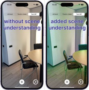
The ARConfiguration and ARView must be properly configured to ensure that objects remain anchored in the scene, physics simulation works correctly, and Person Segmentation is explicitly enabled. This allows for accurate depth layering of virtual content relative to real-world people, both visually and during interaction.


func setupSession() -> ARView {
    // Setup ARView with options
    arView.session.delegate = self
    arView.environment.sceneUnderstanding.options = []
    arView.environment.sceneUnderstanding.options.insert(.occlusion)
    arView.environment.sceneUnderstanding.options.insert(.physics)
    arView.debugOptions.insert(.showSceneUnderstanding)
    arView.renderOptions = [.disableDepthOfField, .disableMotionBlur]
    arView.automaticallyConfigureSession = false
    
    // Setup ARConfiguration with options
    configuration.environmentTexturing = .automatic
    configuration.sceneReconstruction = .meshWithClassification
    configuration.frameSemantics.insert(.personSegmentationWithDepth)
    configuration.planeDetection = [.horizontal, .horizontal]
    
    return arView
}

Person Segmentation Feature

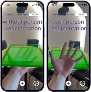
Below is the visual difference when using personSegmentationWithDepth.

By analyzing each ARFrame from the ARSession, the system automatically utilizes depth data and the associated depth map to determine the relative position of the user’s limbs within the scene.

As a result, the user is not visually occluded by overlapping scene objects, allowing for clearer orientation and smoother interaction with virtual elements.

App screens with and without person segmentation

Scene Understanding Feature

By enabling scene understanding through showSceneUnderstanding for the user preview and using sceneReconstruction as part of the session configuration, we provide additional environmental data and gain the ability to treat real-world surfaces as physical elements.

This allows 3D objects to interact with the physical environment when physics is enabled, deepening the overall experience. There is no need for rigid constraints or artificial boundaries; the real-world floor or tabletop becomes a natural constraint.

For the user, scene understanding is visually represented as a polygonal mesh with color gradients that reflect the depth map relative to the device.

App screen without and added scene understanding

Each camera frame is received through the ARKit session via the didUpdate method.

In real-world conditions, processing all 60 FPS provided by the ARSession on devices like the iPhone 14 Pro is highly demanding and places a significant load on the CPU.

Therefore, we limit the target frame rate to 30 FPS to maintain performance and reduce system strain.


func session(
    _ session: ARSession,
    didUpdate frame: ARFrame
) {
    // Get the current timestamp
    let currentTime = Date()
    // Calculate interval between frames based on the desired FPS
    let fpsTime: Double = 1 / handTrackFps
    
    // Send ARFrame for hand tracking if enough time has passed
    if currentTime.timeIntervalSince(lastObservationTime) > fpsTime {
        lastObservationTime = currentTime
        self.eventSubject.send(.newARFrameForTracking(frame))
    }
}

Gestures Control Feature

The flowchart below illustrates the whole logic of gesture-based interaction in our AR application. Starting from each incoming ARFrame, the system detects hands, analyzes finger positions, and identifies gestures.

Based on the recognized gesture, either “Pinch” or “Index Up”, it either creates a new object or initiates the movement of an existing one.

Flowchart showing the entire logic of gesture-based interaction in an AR application

Hand Tracking Using Vision

For gesture-driven AR control, the key component is the hand detector provided via VNDetectHumanHandPoseRequest. This request can identify up to two hands in the frame and returns landmark points for each, including the position of every finger joint.

This enables the development of real-time finger tracking without the need for external sensors or depth hardware. Vision automatically normalizes the coordinates, allowing seamless use within UIView or ARKit environments.

To implement this functionality, we define our service using the HandTrackingManager protocol. This service handles incoming ARFrames from the ARSession, generates corresponding gesture events, and provides a UIView overlay for visualization.


protocol HandTrackingManager {
    // MARK: - Publisher
    var eventPublisher: AnyPublisher<HandTrackingManagerEvents, Never> { get }
    
    // MARK: - Funcs
    func getHandOverlayView() -> UIView
    func processHands(_ frame: ARFrame)
}

enum HandTrackingManagerEvents {
    case indexFingerGestureActive
    case pinchGestureActive(onScreenPoint: CGPoint)
    case pinchGestureInactive
}

Its main entry point is the processHands function, which takes an ARFrame as input. Each time processHands is called, the frame is processed and passed through a VNDetectHumanHandPoseRequest. The results of this request are then handled by the processObservation() method.


func processHands(_ frame: ARFrame) {
    // Extract pixel buffer from the AR frame
    let pixelBuffer = frame.capturedImage
    // Create Vision request handler with set orientation
    // ARKit provides camera feed in .right orientation
    let imageRequestHandler = VNImageRequestHandler(
        cvPixelBuffer: pixelBuffer,
        orientation: .right,
        options: [:]
    )

    // Perform the hand pose detection request
    try? imageRequestHandler.perform([handPoseRequest])

    // Check if at least one hand was detected
    guard
        let results = handPoseRequest.results,
        let observation = results.first
    else {
        return
    }

    // Process the detected hand observation
    processObservation(observation)
}

The processObservation() call follows a straightforward structure. After retrieving the keypoints for the hands, it triggers the visualization overlay and checks for recognized gestures.

Since we selected simple and intuitive gestures, such as a “pinch” (similar to VisionOS) and an “index finger up” gesture; it’s enough to check for these in a prioritized sequence.


func processObservation(_ observation: VNHumanHandPoseObservation) {
    // Try to extract all landmarks from detected observation
    guard
       let recognizedPoints = try? observation.recognizedPoints(.all)
    else {
       return
    }

    handVisualize(points: recognizedPoints)
        
    // Check for pinch gesture and emit corresponding event if detected
    if checkPinchGesture(recognizedPoints: recognizedPoints) {
        return
    }
    // Check for index finger pointing gesture and emit event if detected
    else if indexFingerGesture(recognizedPoints: recognizedPoints) {
        return
    }
}

It’s worth noting that the visualization layer supports multiple display modes, which we will use throughout the application. For preview purposes, we include three options: All Hand, Thumb + Index Fingers, and Turn Off (disable overview).

App screens with gesture recognition

Gesture recognition is based on analyzing the key joint points of the hand. For the “pinch” gesture, we specifically check the distance between the tips of the index finger and the thumb.

Since these coordinates are provided in a 2D screen coordinate system, we must define a trigger threshold, meaning the distance at which the gesture is considered active.


func checkPinchGesture(
   recognizedPoints: [VNHumanHandPoseObservation.JointName: VNRecognizedPoint]
) -> Bool {
    // Try to get positions and confident
    // of the thumb and index finger tips
    guard
        let thumbPoint = recognizedPoints[.thumbTip],
        let indexPoint = recognizedPoints[.indexTip],
        // Check confidences
    else {
        // If any point is missing or not confident enough, 
        // consider pinch inactive
        self.eventSubject.send(.pinchGestureInactive)
        return false
    }
        
    // Calculate distance between thumb and index finger tips
    let dx = thumbPoint.location.x - indexPoint.location.x
    let dy = thumbPoint.location.y - indexPoint.location.y
    let distance = sqrt(dx * dx + dy * dy)
        
    // If the distance is small enough, consider it a pinch gesture
    if distance < expectedDistance {
        // Convert the thumb tip point to screen coordinates
        let screenPoint = convertToScreenSpace(indexPoint.location)
        // Notify system that pinch gesture is active
        self.eventSubject.send(
            .pinchGestureActive(onScreenPoint: screenPoint)
        )
        return true
    } else {
        // Otherwise, treat it as inactive
        self.eventSubject.send(.pinchGestureInactive)
        return false
    }
}

The processing for indexFingerGesture() is even simpler. It only requires checking the alignment of three consecutive joint points along the index finger to determine if the finger is extended and pointing.


func indexFingerGesture(
    recognizedPoints: [VNHumanHandPoseObservation.JointName: VNRecognizedPoint]
) -> Bool {
    // Try to get the required index finger joints
    guard
        let indexTip = recognizedPoints[.indexTip],
        let indexDIP = recognizedPoints[.indexDIP],
        let indexPIP = recognizedPoints[.indexPIP],
        // Check confidences
    else {
        // If any point is missing or not confident enough, 
        // gesture is not valid
        return false
    }
    
    // Collect horizontal x-values of index finger joints
    let xValues: [CGFloat] = [  get index’s X locations ]
    
    // Ensure we can compute the spread of x-values
    guard let maxX = xValues.max(), let minX = xValues.min() else {
        return false
    }
    
    // If finger is mostly vertically aligned (x spread is small),
    // it's considered an active index finger gesture
    if maxX - minX <= expectedRange {
        self.eventSubject.send(.indexFingerGestureActive)
        return true
    } else {
        return false
    }
}

This solution fully isolates the gesture recognition logic from the rest of the application. The ARManager simply provides frames, while the HandTrackingManager is responsible for analyzing them and making decisions based on finger tracking.

Extended Reality: Combination of Elements

It’s time to bring together the services we’ve built into a complete solution that enables real-time gesture-based interaction with the AR scene.

Let’s recall the signal flow diagram shown below.

At the center is the MixedRealityManager, which acts as the coordinating layer. Using Combine, we can subscribe to event updates from our services and organize the desired sequence of operations accordingly.

Diagram showcasing AR session with MixedRealityManager

Step 1: Obtain the ARFrame

The first step is obtaining the ARFrame. ARKit automatically generates ARFrame objects during each session update.

The ARManager intercepts these frames via the session(_:didUpdate:) delegate method described earlier and sends them through a Combine stream to the MixedRealityManager at a defined FPS. These frames serve as the foundation for gesture detection.

Step 2: Pass the Frame

The second step is to pass the frame to the HandTrackingManager. The MixedRealityManager calls the processHands() method and provides the latest ARFrame.

Step 3: Recognize the Gesture

The third step is gesture recognition. If the HandTrackingManager detects one of the expected gestures (such as pinch or index finger), it publishes an event through the Combine stream.

The MixedRealityManager, which is subscribed to these events, executes the corresponding logic, such as adding a new object or activating sandbox movement.

Final Step: Issue the Command

The final step is issuing a command to change the AR scene. Depending on the recognized gesture, the MixedRealityManager triggers the appropriate function to interact with the scene.

A key aspect of the implementation is that all scene control events are routed back to the ARManager. For instance, during a pinch gesture, the screen coordinates are converted into 3D space, and the object’s position is updated accordingly.

The MixedRealityManager does not contain any direct logic for modifying the scene, as that responsibility lies entirely with the ARManager. This separation of layers makes it easy to adjust behavior, introduce new gesture types, or update the UI without affecting the low-level logic.

Extended Reality Project Results: Demos

Below are the final demos showcasing the selected gestures and deeper scene interaction, where the entire surrounding environment becomes part of the AR scene, enabling physical interaction with virtual objects.


It’s worth highlighting the accuracy of the visualization provided to the user through ARView. In addition to generating a polygonal mesh at the start of the ARSession, the mesh is dynamically updated as the device or real-world objects move. This enables the system to avoid phantom boundaries, resulting in a smoother and more immersive experience.


This is a truly exceptional and unique experience today. The ideas demonstrated above represent not just a step, but a new direction in the evolution of user experience. With modern processing power, high-quality camera sensors, lightweight models, and rapidly advancing tools, we can now create experiences that were once considered science fiction.

Final Word on the Extended Reality Project

Gesture-based interaction in AR is no longer just a technical challenge; it is a real step beyond traditional UX thinking.

This project successfully combined the power of computer vision, via the Vision Framework, with the spatial capabilities of ARKit to create a path toward XR experiences that are free of physical interfaces.

From a business perspective, such solutions introduce new interface models for AR apps, especially in the emerging market of wearable consumer tech. This isn’t innovation for its own sake; it’s a new entry point into digital interaction, a bridge to expanded toolsets and digital learning.

The scalability of these approaches extends beyond B2C, offering tremendous potential in the B2B sector.

  • In manufacturing, a mechanic assembling a vehicle can visualize a 3D part model directly in their workspace.
  • In healthcare, surgeons can navigate pre-op environments without physical contact.
  • In logistics, workers can manage alerts, cargo, and automation without being tethered to a console. The full potential is yet to be uncovered.

Technically, this project delivers a working foundation that is modular, scalable, and reliable. With clearly separated services, multithreaded execution, and architecture built for extension, it enables both experimentation and product development.

Our prototype is not just a showcase. It’s a foundation. A step, not sideways, but forward on a path that leads into a new market and a new interface paradigm. We’re already here, and we’re moving ahead.

What kind of experience are you expecting from personal MR devices?

Your idea could be the next stage in this journey.

3D Reconstruction on iOS: Ultimate Guide with Code Samples

Ultimate Tutorial to 3D Reconstruction on iOS: Key Techniques, Differences, & Workflow

In the fast-changing world of mobile technology, 3D model reconstruction on handheld devices is a big leap forward. Algorithms like SLAM, Voxel-Based Reconstruction, and Point Cloud Reconstruction help create 3D models from captured images.

Traditionally, these computationally intensive processes required desktop computers. In contrast, mobile devices are limited to data collection due to their constrained CPU/GPU, memory, and storage.

Apple’s ObjectCapture has changed the game. It enables high-quality 3D model creation directly on mobile devices.

Introduced at WWDC21 for macOS, the technology was initially used for data collection on iOS devices. From WWDC23 and iOS 17, ObjectCapture now supports full 3D reconstruction on iPhones and iPads.

This comprehensive guide on building 3D reconstruction solutions will cover:

  • ObjectCapture’s features for capturing objects and creating 3D reconstructions
  • Different output data structures of ObjectCapture. 
  • Limitations encountered during ObjectCapture integration. 
  • Real-world use cases of ObjectCapture for 3D reconstruction on iOS.
  • Alternative data capture methods: RoomPlan, AVCaptureSession, Photogrammetry.
  • Code samples for each data capture method.
  • A detailed comparison of data-capturing methods for the best results.

Let’s start by examining the workflow and specifics of ObjectCapture.

Overview of ObjectCapture Workflow for 3D Reconstruction

It is essential to understand the general workflow for creating a 3D object directly on an iPhone or iPad using the ObjectCapture API.

The entire process can be divided into two main stages:

  1. Capturing the input data
  2. Reconstructing the object with the captured data

In the first stage, you use your device’s camera to take many photos of the object from various angles. The quality and coverage of these images directly impact the accuracy of the final 3D reconstruction model.

Scheme of 3D reconstruction flow

During the second stage, the ObjectCapture API processes the captured images. The API checks the photos and combines them to make a detailed 3D visualization of the object, including precise texture, color, and shape.


Interested to learn about 3D reconstruction on iOS and other innovative technologies?

Reach out to our team for an individual consultation. Learn how to utilize 3D computer vision services and machine learning capabilities in your business or next big project. With a deep understanding of technologies and 10+ years of experience, we ensure you achieve the most value and results.

Contact us


3D Reconstruction on iOS with ObjectCapture API

ObjectCapture API is a tool for high-quality data capture. 

Data capture is the essential step in 3D object reconstruction. This process is not just about snapping a few photos. It is about preparing the foundation for a precise and detailed 3D model.

The accuracy and quality of the final 3D reconstruction on iOS are directly tied to how well the images are taken. Recording every angle and detail of the object ensures the most accurate and realistic result.  

The capturing process splits into “scan passes.” These substages create images of the object from different angles and collect extra data. ObjectCapture’s UI shows areas where more images are needed and gives tips to improve shot quality. 

ObjectCapture has an easy-to-use interface. It helps users collect data and offers visual cues to navigate around the object. It captures frames, records camera poses, and creates depth maps automatically. This makes the 3D reconstruction process easy and accessible for users.

Thus, this functionality integrates into the app using:

  1. ObjectCaptureView provides a user interface that guides the user through the capturing flow.
  2. ObjectCaptureSession performs data capturing and prepares the data source for further reconstruction. 
  3. Behind the scenes, ObjectCaptureSession relies on ARSession.

High-level view of the 3D object capture process

1. Object Capture View

ObjectCaptureView is a high-level SwiftUI view that encapsulates the entire image capture experience. It provides built-in guidance, visual instructions, and progress tracking as the user walks around an object or environment.

Although ObjectCaptureView is a SwiftUI view, Apple has made it easy to integrate this interface into UIKit-based apps using UIHostingController

This aspect is beneficial for projects that still rely on UIKit but want to take advantage of the latest AR and 3D technologies provided by SwiftUI.

Here’s a simple code example of how to embed ObjectCaptureView into a UIViewController:


struct CaptureView: View {
    // MARK: - Properties
    private let session: ObjectCaptureSession
    
    // MARK: - Init
    init(session: ObjectCaptureSession) {
        self.session = session
    }
    
    // MARK: - Body
    var body: some View {
        ZStack {
            ObjectCaptureView(
                session: session,
                cameraFeedOverlay: {
                    CameraFeedOverlayView()
                }
            )
        }
    }
}

Then, create a UIHostingController with CaptureView as the rootView and add UIHostingController’s view as a subview to your view. 


let hostingController = await UIHostingController(rootView: CaptureView(session: session))

view.addSubview(hostingController.view)

2. Object Capture Session

The ObjectCaptureSession class manages the image capture workflow, dividing the process into structured stages to ensure optimal data collection.

Users are guided through each stage via the ObjectCaptureView, which overlays helpful instructions and feedback directly onto the camera interface.

Let’s take a look at an example of how to utilize ObjectCaptureSession to capture images for 3D reconstruction on iOS.

For this purpose, we created an ObjectCaptureService, which is responsible for managing all stages of data capture using ObjectCaptureSession:


protocol ObjectCaptureService {
    // MARK: - Publishers
    var eventPublisher: AnyPublisher&amp;amp;lt;ObjectCaptureServiceEvent, Never&amp;amp;gt; { get }
    
    // MARK: - Functions
    func setImagesFolder(folder: URL)
    
    func getPointCloudView()
    
    func isFlippableObject(completion: @escaping (Bool) -&amp;amp;gt; ())
    func start()
    func finish()
    func pause()
    func resume()
    func cancel()
    func startDetecting()
    func resetDetecting()
    func startCapturing()
    func beginNewScanPass()
    func beginNewScanPassAfterFlip()
}

First, we need to initialize the ObjectCaptureSession. 

To start the session, we provide a path to the folder where the captured images will be saved.


func start() {
        Task { [weak self] in
            if self?.session != nil {
                self?.resetSession()
            }
            self?.session = await ObjectCaptureSession()
            
            guard
                let session = self?.session,
                let imagesFolderUrl = self?.imagesFolderUrl
            else {
                self?.eventSubject.send(.failed(errorMessage: "Unable to create session"))
                return
            }
            
            var configuration = ObjectCaptureSession.Configuration()
            configuration.isOverCaptureEnabled = true
            
            await session.start(
                imagesDirectory: imagesFolderUrl,
                configuration: configuration
            )
            
            self?.setupBindings()
             
            await self?.eventSubject.send(.captureView(view: .init(rootView: .init(session: session))))
        }
    }

We must set up bindings to receive updates on camera tracking, session state, and completed scan passes. This action helps us manage the session and give users the proper instructions. 


func setupBindings() {
        tasks.append(
            Task { [weak self] in
                guard let session = self?.session else {
                    return
                }
                for await cameraTracking in await session.cameraTrackingUpdates {
                    self?.cameraTrackingState = cameraTracking
                }
            }
        )
        
        tasks.append(
            Task { [weak self] in
                guard let session = self?.session else {
                    return
                }
                for await sessionState in await session.stateUpdates {
                    self?.sessionState = sessionState
                }
            }
        )
        
        tasks.append(
            Task { [weak self] in
                guard let session = self?.session else {
                    return
                }
                for await scanPassUpdate in await session.userCompletedScanPassUpdates {
                    self?.eventSubject.send(.scanPassCompleted(success: scanPassUpdate))
                }
            }
        )
    }

3. Object Mode

In Object mode, ObjectCapture focuses on 3D scanning distinct items placed on a surface.

This mode is perfect for digitizing individual products or artifacts. The bounding box becomes particularly important here, helping to estimate the object’s real-world dimensions and ensuring accurate scaling.

Object mode is most effective when the target item is well-lit, visually distinct from the background, and positioned so the user can easily walk around it. The mode supports single-side or multi-side captures based on the object’s orientation and complexity.

After selecting an object to capture, it is necessary to define its bounding box. ObjectCaptureView allows users to adjust its position and size to ensure sufficient coverage easily. This stage is critical to ensure that the size of the produced model will be close to the real-life one. Also, it helps with further user guidance through flow capturing.

Therefore, capturing the object in 3D involves three steps:

  • Selecting a target object.
  • Defining a bounding box.
  • Capturing an object.

Process of 3D object capturing on iOS


These steps correspond to the methods of ObjectCaptureSession:

Steps of an object capture session

In Object mode, ObjectCapture indicates if an object is flippable, prompting users to rotate the object and recapture it. Although this process requires redefining the bounding box, it ensures that the 3D reconstruction fully captures all sides of the object. 

4. Area Mode

Area mode expands ObjectCaptureView’s scanning capabilities beyond single objects, enabling users to capture large physical spaces such as rooms, hallways, large installations, and entire environments​.

This mode is helpful for applications that require a spatial understanding of surroundings, such as interior design, architecture, construction, and real estate.

In this mode, the user is guided to move around a space, capturing overlapping images from different angles and heights.

Unlike Object mode, where the subject is central and isolated, Area mode requires broader spatial scanning and more extensive user movement.

Area mode in iOS 3D scanning


In Area mode, there is no need to define a bounding box, which simplifies the capturing process into two steps:

Steps in Area mode

3D Reconstruction on iOS: Pros & Cons of  Object Capture API

While the ObjectCapture API simplifies image capturing and provides a user-friendly experience, there are also some limitations to be aware of when integrating it into apps.

The advantages of using 3D reconstruction on iOS include:

1. Integrated visual guidance

Provides real-time visual cues that help users properly scan an object or scene. It highlights areas that require more image coverage and offers feedback on image quality and coverage. 

2. Flippable object support 

The API detects whether an object should be flipped to capture unseen areas. This feature leads to more complete reconstructions, especially for complex shapes.

3. Automatic frame capturing

Frames are captured automatically when optimal angles and stability are detected. This functionality reduces motion blur and ensures even spacing, simplifying the workflow and improving output quality.

4. Platform-optimized and energy-efficient

Object Capture is aware of system resources, dynamically adjusting capture behavior to maintain efficiency on iPhone and iPad.

The disadvantages of creating 3D reconstruction solutions with ObjectCapture are as follows:

1. Fixed image format

All captured images are stored in HEIC format. While efficient, this may not be a good match if you need other image formats in specific cases.

2. Limited customization of capture flow

Developers can not modify camera behavior, such as frame capture rate, focus, or exposure. 

3. No real-time frame access

Captured frames are not accessible in real-time, which restricts the ability to run custom processing (such as machine learning or computer vision tasks). There are still options to access frames during capturing, but ObjectCapture does not provide an API for this function.

4. Non-customizable capture UI

The default ObjectCaptureView has a fixed appearance and user interaction flow. Developers can not modify styling, which can be limiting for apps that require a customized or branded UI.

Data Capturing with RoomPlan

Apple RoomPlan API is a robust framework that helps developers capture and map indoor environments accurately.

It leverages the power of iPhone sensors, such as LiDAR technology, to create 3D model reconstruction of room layouts, including structures such as walls, furniture, and doors.

The framework provides RoomCaptureSession, which allows developers to capture an entire room or environment seamlessly. This technology is ideal when the goal is to map a whole indoor space and understand the relationship between different objects within that space rather than focusing on a specific object.

RoomCaptureSession extends ARSession by adding the capability to scan and map entire indoor environments, reconstructing the layout of a room along with its structures, such as walls, furniture, and doors.

This scan produces a 3D reconstruction that captures the space’s general structure and geometry. You can utilize PhotogrammetrySession to achieve a more detailed reconstruction with fine textures, subtle color variations, and intricate details.

Using this approach, we can capture frames with ARSession and process them with PhotogrammetrySession while obtaining the data that RoomCaptureSession captured.

Room Plan Benefits of 3D Reconstruction on iOS

By combining these datasets, developers can significantly enrich their models. This combined approach allows the following advantages of 3D reconstruction:

1. Incorporating texture and color

RoomCaptureSession provides structural data of a room, while PhotogrammetrySession can capture detailed textures and colors. This approach makes the environment feel more lifelike and visually appealing. This can be particularly useful for interior design apps, architectural 3D visualizations, and furniture previews.

2. Reconstructing entire rooms

This approach creates immersive AR experiences where users can interact with the entire environment rather than just isolated objects.

RoomPlan: Code Implementation and Key Considerations

To integrate RoomCaptureSession for capturing objects in 3D, we created a separate service called RoomCaptureService.


protocol RoomCaptureService {
    // MARK: - Publishers
    var eventPublisher: AnyPublisher&amp;amp;lt;RoomCaptureServiceEvent, Never&amp;amp;gt; { get }
    
    // MARK: - Functions
    func setup(configuration: RoomCaptureConfiguration)
    
    func start()
    func pause()
    func stop()
}

We need to conform our service to two delegates:

  • RoomCaptureSessionDelegate to receive RoomCapturedData. 
  • ARSessionDelegate to handle individual frames.

   // MARK: - RoomCaptureSessionDelegate
extension RoomCaptureServiceImpl: RoomCaptureSessionDelegate {
    func captureSession(
        _ session: RoomCaptureSession,
        didEndWith data: CapturedRoomData,
        error: (any Error)?
    ) {
        guard error == nil else {
            DispatchQueue.main.async { [weak self] in
                self?.prepareCaptureView(reset: true)
                self?.roomCaptureView?.captureSession.run(configuration: .init())
            }
            return
        }
        captureFrames = false
        eventSubject.send(.didEnd(data: data))
    }
    
    func captureSession(
        _ session: RoomCaptureSession,
        didUpdate room: CapturedRoom
    ) {
        if !captureFrames {
            captureFrames = true
        }
    }
}
// MARK: - ARSessionDelegate
extension RoomCaptureServiceImpl: ARSessionDelegate {
    func session(
        _ session: ARSession,
        didUpdate frame: ARFrame
    ) {
        guard isValid(frame: frame), captureFrames else {
            return
        }
        updateFrame()
    }
}

To avoid capturing redundant frames, we implemented frame validation logic. There are several options to do that. 

One approach is to compare the camera transform’s position and angle of the current frame with the previous one. 

If they are nearly identical, the frame is skipped; if they differ, the frame is saved. This method significantly reduces frame count while preserving key frames.


func isValidFrame(currentTransform: simd_float4x4) -&amp;amp;gt; Bool {
        guard let previousTransform else {
            self.previousTransform = currentTransform
            return true
        }
        
        let angle = currentTransform.angle(to: previousTransform)
        let distance = currentTransform.distance(to: previousTransform)
        
        guard
            angle &amp;amp;gt; (RoomCaptureConstants.rotationThreshold / 180) * .pi ||
            distance &amp;amp;gt; RoomCaptureConstants.distanceThreshold
        else {
            return false
        }
        self.previousTransform = currentTransform
        
        return true
   }

Another option is to use the frame timestamp and compare it against a specified FPS (frames per second) to reduce the number of frames captured.


func isValidFrame(currentTimestamp: Double, fps: Int) -&amp;amp;gt; Bool {
        guard let previousTimestamp else {
            self.previousTimestamp = currentTimestamp
            return true
        }
        
        let difference = currentTimestamp - previousTimestamp
        let framesCapturingTimeDelta = 1 / Double(fps)
        if difference &amp;amp;gt;= framesCapturingTimeDelta {
            self.previousTimestamp = currentTimestamp
            return true
        } else {
            return false
        }
    }

Table capturing with RoomCaptureSession

Pros & Cons: 3D Reconstruction on iOS with Room Plan 

Now, let’s examine the advantages and disadvantages of using ARSession when capturing photogrammetry and 3D object reconstruction data.

Advantages of 3D reconstruction with RoomPlan:

  • Provides rich spatial data: meshes, camera positions, and scene structure.
  • Includes RGB and depth data.
  • It is useful when capturing and reconstructing entire rooms and spaces.
  • You can obtain real-time frames for custom processing.

Disadvantages of using RoomPlan for 3D reconstruction:

  • Not optimized for isolated object capture.
  • 3D reconstructions may lack fine details or have sections that appear blurry.
  • Developers must implement custom logic for frame validation and capture flow to ensure helpful photogrammetry input.
  • Developers need to implement user guidance for high-quality results.

Data Capturing with AVCaptureSession

AVCaptureSession is another powerful component of the AVFoundation framework that grants full access to camera input on iOS devices.

This technology allows developers to create highly customizable and versatile capture experiences, providing the ability to capture still images, record videos, and handle metadata with complete control.

With AVCaptureSession, you can fine-tune nearly every aspect of image and video capture, such as image resolution, exposure, white balance, and focus. These features allow developers to adapt the capture process to meet specific requirements. Depending on your needs, AVCaptureSession can be tailored to provide manual or automatic frame capturing.

AVCaptureSession can capture high-quality, still photos from various angles for 3D object reconstruction using PhotogrammetrySession. Unlike ObjectCaptureSession, it allows you to fully customize the user interface (UI) and the capture experience.

Benefits of Using AVCaptureSession for 3D Reconstruction

You can design your UI to match the specific needs of your application, whether it’s guiding users through the scanning process or providing manual controls for advanced users, namely:

  • On-screen overlays and instructions

You can implement custom on-screen overlays that guide users step-by-step through 3D scanning on iOS. This approach can include visual cues, like highlighting the area to focus on, showing the ideal positioning for objects, or displaying a progress bar indicating when enough frames have been captured.

  • Interactive experience

Developers can add interactive elements that allow users to manually adjust camera settings such as focus, exposure, or resolution.

  • Automatic or manual capture modes

Developers can use AVCaptureSession to create different user experiences. If your app lets users move around an object, it can capture frames automatically.

If they need to take photos manually, AVCaptureSession can handle that, too. This functionality allows you to design the flow and capture the best experience.

AVFoundation provides access to supplementary data, such as depth information and camera calibration, along with captured frames. You can use this for advanced processing or specific data capture needs.

AVCaptureSession: Code Implementation and Key Considerations

To implement frame capturing with AVCaptureSession, we created a service called AVSessionManager.


protocol AVSessionManager: AnyObject {
    // MARK: - Publishers
    var eventPublisher: AnyPublisher&amp;amp;lt;AVSessionManagerEvent, Never&amp;amp;gt; { get }
    
    // MARK: - Functions
    func setup(mode: AVCaptureMode) -&amp;amp;gt; AVCaptureVideoPreviewLayer
    
    func start()
    func stop()
    
    func capture()
    func focus(on point: CGPoint)
}

There are several options for capturing frames for object reconstruction using AVCaptureSession.

The first option is to use AVCapturePhotoOutput for manual capture. Here, the user must take the needed number of photos.

AVCapturePhotoOutput provides high-quality images and allows customization of photo settings (e.g., format). It can also capture depth data if available. When you save the photo with fileDataRepresentation, it also automatically saves the metadata and depth data.

When users take photos manually, they might miss some parts of the object. This can lead to not having enough common points for photogrammetry. Additionally, this method can be inconvenient for end-users.

Thus, to capture frames using AVCapturePhotoOutput, we must do a few things:

  • Add photo output to the capture session.
  • Set up the photo settings.
  • Implement the AVCapturePhotoCaptureDelegate protocol to manage the captured photos.

  // MARK: - Photo settings
private extension AVSessionManagerImpl {
    func getPhotoSettings() -&amp;amp;gt; AVCapturePhotoSettings {
        var settings = AVCapturePhotoSettings()
        
        if photoDataOutput.availablePhotoCodecTypes.contains(.hevc) {
            settings = AVCapturePhotoSettings(format: [AVVideoCodecKey: AVVideoCodecType.hevc])
        }
        
        settings.embedsDepthDataInPhoto = true
        settings.photoQualityPrioritization = .quality
        settings.isDepthDataDeliveryEnabled = photoDataOutput.isDepthDataDeliverySupported
        
        return settings
    }
}


// MARK: - AVCapturePhotoCaptureDelegate
extension AVSessionManagerImpl: AVCapturePhotoCaptureDelegate {
    func photoOutput(
        _ output: AVCapturePhotoOutput,
        didFinishProcessingPhoto photo: AVCapturePhoto,
        error: Error?
    ) {
        eventSubject.send(.photo(photo: photo))
    }
}

Save the captured photo using fileDataRepresentation in the image folder. This way, it can be used later in the PhotogrammetrySession.

Capturing a speaker 3D model with AVCaptureSession


Another option is to use AVCaptureVideoDataOutput with a specified frame rate.

In this case, frames are captured and saved automatically. The user just needs to move the camera around the object they want to capture.

Yet, additional setup is required to capture depth data along with the RGB frames.

Furthermore, when you save an image from a CMSampleBuffer, the metadata and depth data necessary for 3D reconstruction on iOS aren’t automatically saved with the image. We must handle this explicitly during the saving process.

We need to do a few things to save everything correctly:

  • First, convert the CMSampleBuffer to a CGImage. 
  • Then, extract the metadata from the CMSampleBuffer. 
  • Finally, save the image, metadata, and depth data using CGImageDestination to the designated image folder.

 func saveImageWithMetadata(
        to url: URL,
        cgImage: CGImage,
        metadata: [String: Any],
        depth: AVDepthData?
    ) -&amp;amp;gt; URL? {
        guard
            let destination = CGImageDestinationCreateWithURL(url as CFURL, AVFileType.heic as CFString, 1, nil)
        else {
            return nil
        }
        CGImageDestinationAddImage(destination, cgImage, metadata as CFDictionary)
        if var depthDict = depth?.dictionaryRepresentation(forAuxiliaryDataType: nil) {
            depthDict.removeValue(forKey: kCGImageAuxiliaryDataInfoMetadata)
            CGImageDestinationAddAuxiliaryDataInfo(
                destination,
                kCGImageAuxiliaryDataTypeDisparity,
                depthDict as CFDictionary
            )
        }
        
        if !CGImageDestinationFinalize(destination) {
            return nil
        }
        
        return url
    }


 func process(
        buffer: CMSampleBuffer,
        depth: AVDepthData?,
        index: Int
    ) {
        guard let outputFolder else {
            return
        }
        
        processingQueue.addOperation { [weak self] in
            let frameName = "\(index)_\(OutputProcessingConstants.frameFileName)"
            let url = outputFolder.appendingPathComponent(frameName)
            guard let cgImage = buffer.cgImage else {
                return
            }
            
            let metadata = CMCopyDictionaryOfAttachments(
                allocator: kCFAllocatorDefault,
                target: buffer,
                attachmentMode: kCMAttachmentMode_ShouldPropagate
            ) as? [String: Any] ?? [:]
            guard
                let rgbFile = self?.saveImageWithMetadata(
                    to: url,
                    cgImage: cgImage,
                    metadata: metadata, 
                    depth: depth
                )
            else {
                self?.eventSubject.send(.error(message: "Failed to save image"))
                return
            }
            
            self?.eventSubject.send(.output(url: rgbFile))
        }
    }


Scanning an object to create 3D model

Pros & Cons of AVCaptureSession for 3D Reconstruction

When using AVCaptureSession for 3D object reconstruction, it is vital to consider its flexibility and challenges.

Advantages of using AVCaptureSession as a 3D reconstruction solution:

  • Complete control over image capture parameters, allowing for precise customization.
  • Ideal solution for custom capture workflows.
  • Easy to integrate with custom user interfaces or capture guidance overlays.
  • Real-time access to frames for custom processing.
  • Capability to capture and save additional data, such as depth data and camera calibration.
  • It supports saving frames in various image formats, including HEIC, JPEG, etc.

Disadvantages of utilizing AVCaptureSession for 3D reconstruction on iOS:

  • It requires manual implementation and organization of image saving.
  • No automatic mesh generation or object detection.
  • More development effort is needed to create a fully functional scanning experience.
  • It may not produce the highest quality 3D models compared to results obtained with ObjectCaptureSession.

3D Reconstruction on iOS: Comparison Table of Object Capturing Methods 

Let’s make a final comparison to summarize the main distinctions among ObjectCaptureSession, RoomCaptureSession, and AVCaptureSession.

The table below provides a clear overview and helps you determine which 3D reconstruction solution best fits your automation, flexibility, and data richness needs.

Criteria ObjectCaptureSession RoomCaptureSession AVCaptureSession
User Guidance Built-in visual guidance and quality feedback Semantic feedback only (e.g., walls, doors highlighted); no active guidance Fully custom implementation required
Automation Auto frame capture at optimal angles Manual frame capture and logic implementation Manual frame capture and logic implementation
Real-time Frame Access No  Yes Yes
Camera Parameter Control No control No control Full control (focus, exposure, etc.)
UI Customization Limited Limited Fully customizable
Data Richness Only RGB images in HEIC format RGB, depth, mesh, camera transform RGB, depth, calibration data
Supported Image Formats Only HEIC format HEIC, JPEG, and more HEIC, JPEG, and more
Scene Coverage Supports flippable object logic for full coverage Great for full-room reconstruction Requires manual logic to ensure sufficient coverage
Mesh Generation No  Provides a mesh of the room, environment No 
Ideal For Isolated object reconstruction with minimal setup Room-scale scanning and reconstruction Custom capture workflows with high flexibility
Development Effort Minimal, high-level API Moderate, custom logic needed High, everything must be implemented manually
Output Quality High quality for objects, moderate for areas Moderate, can lack fine detail Varies, depends on implementation and captured images

Photogrammetry: 3D Reconstruction Technology 

Photogrammetry is a technique for reconstructing 3D models. It analyzes multiple overlapping 2D images of an object or environment to find key points, measure their relative positions, and rebuild the object’s shape and texture in 3D.

Photogrammetry transforms flat photos into detailed and accurate 3D visualizations by combining geometric algorithms with photometric consistency.

The 3D reconstruction process using photogrammetry involves multiple stages, which are performed to produce a precise model. These stages include:

1. Pre-processing

During this stage, it is crucial to check image quality, make corrections, set the camera’s internal parameters, and handle other preparations.

2. Image alignment

This phase involves adjusting and coordinating multiple images. They need to overlap and match correctly in 3D space.

3. Point cloud generation

This stage creates a 3D representation of an object by collecting and analyzing data from multiple images. It transforms 2D image information into a spatially accurate 3D model.

4. Mesh generation

This step involves converting a point cloud into a detailed 3D surface mesh. The process creates a polygonal model that represents the surface geometry of the scanned object.

5. Texture mapping

The texture mapping stage adds detailed textures, like color and surface details, to a 3D mesh. This method helps create a realistic look for the scanned object.

6. Optimization

This stage refers to refining the parameters of a 3D model. The goal is to reach the best accuracy and quality.

Photogrammetry on iOS: How to Use 3D Reconstruction

You can use the PhotogrammetrySession from the ObjectCapture API for 3D reconstruction on iOS with photogrammetry.

As a result of reconstruction, PhotogrammetrySession can produce different types of output data. This data can then be used in more complex processing pipelines.

Reconstruction allows PhotogrammetrySession to create various output data types. This data can then be used in more complex processing pipelines.

Let’s consider how we can reconstruct 3D models from a series of captured images.

We created a separate ReconstructionService, which is responsible for managing the photogrammetry process:


protocol ReconstructionService {
    // MARK: - Publishers
    var eventPublisher: AnyPublisher&amp;amp;lt;ReconstructionServiceEvent, Never&amp;amp;gt; { get }
    
    // MARK: - Functions
    func setOutputFolder(outputFolder: URL)
    
    func getModelFilePath() -&amp;amp;gt; URL?
    
    func start(configuration: ReconstructionServiceConfiguration)
    func cancel()
}
 

To start a session, we need to specify a configuration and the path to the folder where all captured images are stored.

We also need to identify the output requests we are interested in.


func start(configuration: ReconstructionServiceConfiguration) {
        var sessionConfiguration = PhotogrammetrySession.Configuration()
        sessionConfiguration.featureSensitivity = configuration.featureSensitivity
        sessionConfiguration.sampleOrdering = configuration.sampleOrdering
        sessionConfiguration.isObjectMaskingEnabled = configuration.isObjectMaskingEnabled
        
        guard
            let imagesFolderUrl,
            let modelFilePath,
            let session = try? PhotogrammetrySession(
                input: imagesFolderUrl,
                configuration: sessionConfiguration
            )
        else {
            eventSubject.send(.failed(errorMessage: "Session creation failed"))
            return
        }
        
        photogrammetrySession = session
        
        startObserving(outputs: session.outputs)
        
        do {
            try session.process(requests: [
                .modelFile(url: modelFilePath),
                .pointCloud,
                .poses
            ])
        } catch {
            eventSubject.send(.failed(errorMessage: error.localizedDescription))
        }
    }

Available PhotogrammetrySession.Request types and their corresponding output data include:

  1. modelFile – USDZ file with the reconstructed object.
  2. modelEntityan in-memory 3D object that can be directly used in the app.
  3. bounds – precise bounding box of the object, which was reconstructed.
  4. pointCloud – PointCloud, which was created during the reconstruction flow.
  5. poses – estimated sample pose using the 6DOF (Six Degrees of Freedom) algorithm.

Available PhotogrammetrySession.Configuration options include:

  1. featureSensivity
  2. sampleOrdering
  3. isObjectMaskingEnabled

Configurations of Photogrammetry Session on iPhone

To receive updates and output data, we need to start observing the session’s outputs:


func startObserving(outputs: PhotogrammetrySession.Outputs) {
        Task { [weak self] in
            guard let self = self else {
                return
            }
            
            let outputs = UntilProcessingCompleteFilter(input: outputs)
            
            for await output in outputs {
                switch output {
                case .requestError(let request, let error):
                    if case .modelFile = request {
                        self.eventSubject.send(.failed(errorMessage: error.localizedDescription))
                    }
                    
                case .requestComplete(_, let result):
                    switch result {
                    case .pointCloud(let pointCloud):
                        self.savePointCloud(output: pointCloud)
                        
                    case .poses(let poses):
                        self.savePoses(output: poses)
                        
                    default:
                        continue
                    }
                    
                case .processingComplete:
                    self.saveCapturedImagesMetadata()
                    self.eventSubject.send(.completed(output: self.outputFolderUrl))
                    self.photogrammetrySession = nil
                    
                case .processingCancelled:
                    self.photogrammetrySession = nil
                    break
                   
                case .inputComplete:
                    break
                    
                case .requestProgress(let request, let fractionComplete):
                    if case .modelFile = request {
                        self.eventSubject.send(.progress(value: Float(fractionComplete)))
                    }
                    
                case .requestProgressInfo(let request, let progressInfo):
                    if case .modelFile = request {
                        let remainingTime = progressInfo.estimatedRemainingTime
                        self.eventSubject.send(.remainingTime(interval: remainingTime))
                        
                        let processingStage = progressInfo.processingStage?.processingStageString
                        self.eventSubject.send(
                            .processingStage(description: processingStage ?? Strings.Reconstruction.processing)
                        )
                    }
                    
                default:
                    continue
                }
            }
        }
    }

We can retrieve valuable information from the session outputs. This includes the current processing stage and the estimated time left for processing. This data helps improve user experience by providing real-time feedback on the 3D reconstruction progress.

By adding these insights to the user interface, we allow users to stay informed and engaged throughout the reconstruction workflow.

Once the 3D reconstruction process is done, ObjectCapture provides a range of detailed outputs. You can access or export these for further use:

1. 3D Model 

The primary output is a high-quality 3D model of the scanned object or area, exported in USDZ format.

2. Bounds

The precise bounding box of the reconstructed object represents its size and spatial limits in 3D space.

3. Captured Images

All source images used during the photogrammetry session are preserved and can be exported for further processing, analysis, or archiving.

4. Image Metadata

Each captured image contains embedded metadata. This metadata can be extracted and saved separately as a text file.

5. PointCloud 

A point cloud representing the key visual features identified during image alignment can be exported as a plain text file, which is helpful for 3D visualization or custom processing pipelines.

6. Poses 

You can retrieve pose data for each captured image, including translation, rotation, and the extrinsic matrix. This information can be saved to a text file and used in custom processing or workflow analysis.

Exporting a 3D reconstruction of a captured object on an iPhone


Comparison of 3D Reconstruction Solutions on iPhone and Mac

While you can now easily perform a full 3D reconstruction entirely on an iPhone, you can also carry out the photogrammetry process on a Mac.

The core photogrammetry APIs work on both platforms. However, differences in performance, output quality, and features can affect results and user experience based on the device.

The iPhone has notable limitations compared to macOS. Specifically, the iPhone version lacks support for:

  • Multiple mesh types.
  • Different detail levels.
  • Custom detail specifications (e.g., maximum polygon count, texture format selection,  output texture maps, etc.).

These advanced features are available on macOS. This makes the Mac version more flexible. It is better for workflows that need fine-tuning and enhanced control over the final output.

The diagram below showcases how the same set of images can lead to different results based on whether the 3D reconstruction is done on an iPhone or a Mac. This analysis helps developers decide where to run the reconstruction workflow in their apps or pipelines.

To evaluate the differences in performance and output quality, we ran a series of tests on two devices: an iPhone 13 Pro Max and a Mac mini M1 (8 GB RAM). The same image sets and reduced detail levels were used for every reconstruction task. We measured how long each device took to complete the 3D reconstruction on iOS.


Graph photogrammetry 3D reconstruction time iPhone vs Mac

On average, the Mac performed about 4% faster than the iPhone. However, this average hides the fact that performance differences become especially noticeable when scanning larger areas, such as full rooms or complex interior spaces.

For small or single-object scans, the performance on iPhone and Mac was quite close. In some cases, the iPhone even performed faster.

This makes the Mac especially useful for workflows that involve room-scale reconstruction or larger environments, where processing time can grow significantly.

In these cases, the ability to process 3D reconstructions more quickly can improve productivity and reduce bottlenecks, especially in professional applications or iterative scanning tasks.

Regarding quality, both platforms produce visually and structurally similar results when working with simple objects. However, the Mac’s reconstruction results are often slightly better, especially in scenarios involving:

  • Complex geometry.
  • Fine surface details.
  • Irregular or organic shapes.

This means that the iPhone alone is often sufficient and convenient for quick on-site scanning of simple objects, while the Mac can deliver better results for room-scale or complex object scanning.

3D Reconstruction on iOS: To Sum Things Up

ObjectCapture transforms 3D reconstruction on iPhones and iPads, replacing bulky desktops. 

The ObjectCapture API simplifies the 3D reconstruction on iOS into a guided, user-friendly experience, allowing even beginners to produce high-quality 3D models effortlessly.

Object mode ensures precision for small objects, while Area mode offers spatial scanning of larger areas, architecture, or interiors. Despite fixed image formats and limited real-time frame access, it is ideal for AR solutions, product digitization, and more.

RoomCaptureSession excels in precise spatial mapping of large environments. Also, AVCaptureSession offers fine-tuned camera control for detailed object captures. Both these image acquisition methods require more management and setup but provide greater customization.

Thus, object-capturing tools empower programmers to enhance computer vision development services and 3D scanning apps on iOS across diverse use cases.

The general recommendation is to choose:

  • ObjectCapture for quick, reliable models.
  • RoomCaptureSession for spatial accuracy.
  • AVCaptureSession for detailed reconstructions. 

Ultimately, the choice of the technique depends on the desired outcome, whether it is creating high-quality 3D models of small objects, large environments, or anything in between.

ObjectCapture produces a dense textured mesh. That raw output still needs retopology, UV cleanup, and material refinement before it is usable in a game engine, product renderer, or manufacturing workflow. The same cleanup problems arise with AI-generated geometry. Our article AI 3D Generation: From Prototype to Production covers that post-processing pipeline in detail. Most of the same steps apply here.


Have you seen something inspiring in the article and come up with project ideas?

Let’s build it together and explore opportunities to integrate the latest technologies. Whether you want to improve your company operations or launch a new project, we can cover your business needs with cutting-edge solutions and add measurable outcomes.

Contact the It-Jim team for a consultation.


Fiducial Markers Overview: Types, Use Cases, & Comparison Table

Guide to Fiducial Markers: Exploring Types, Applications, and Key Differences

Accurate data tracking and measurement are constant challenges in numerous use cases. Can fiducial markers become a solution? Let’s find out. 

For instance, the medical industry requires colossal accuracy, and even a 1 millimetre deviation can jeopardize a surgery’s outcome.

Misaligned virtual surfaces in AR can disorient users. For instance, some objects may appear closer than their physical counterparts. 

Fiducial markers represent a powerful tool to address these pain points for various applications and computer vision tasks, such as object detection, camera pose estimation, and anything that requires a robust source of image features. 

People often mistakenly think of fiducial markers only as square binary codes, which limits their understanding of their true potential. Fiducials are designed for easy detection in different lighting, angles, and distances, making them reliable tools for real-world settings.

This comprehensive guide delves into the topic and highlights fiducial marker benefits and the following aspects:

  • Types of fiducial markers and their properties. 
  • Applications of fiducial markers across different industries.
  • Comparison of fiducial markers with their strengths and limitations for better decision-making.

Let’s dive right into defining what is a fiducial marker.

What Are Fiducial Markers and Their Benefits

Fiducial markers are created objects like black-and-white grids, checkerboards, or shapes with certain patterns. These markers are set in an environment or scene to help imaging systems find reference points.

The term “fiducial” comes from the Latin – fiducia, meaning trust, reflecting their function as dependable reference points for spatial measurements.

Designed for easy detection by cameras and algorithms, these markers enable precise 3D tracking. Typically, each fiducial marker is part of a system with a detection algorithm and coding. Detecting any marker generally carries information about its location on the image, orientation, and unique ID.

To make things even more straightforward, here is a simple explanation. Since images lose information about the captured scene depth, it is difficult to estimate the dimensions of an existing object properly. 

This issue may be solved by placing an object with well-known dimensions, such as a ruler, in the field of view. In this case, the ruler is a reference point and stands for a fiducial marker.

In computer vision development services, fiducial markers have similar purposes and expand in more ways of estimating camera geometry properties. Cameras can detect and interpret these marked objects to calculate position, orientation, and scale. 


Interested in knowing how to overcome industry challenges with cutting-edge fiducial markers

At It-Jim, you can explore our 10+ years of expertise in building computer vision solutions. We have proven experience designing and integrating various tech systems for existing businesses or new innovative projects. 

Contact us for a consultation


To sum things up, the fiducial marker benefits are as follows:

  • Accuracy: offers reliable reference points for precise positioning, alignment, and tracking. This feature boosts spatial accuracy in complex systems like imaging devices, robots, and AR platforms.
  • Automation: streamlines calibration and alignment. This fiducial marker property enables machines to operate with minimal human help in robotics and automated inspection processes.
  • Repeatability: ensures consistent results in repeated imaging. This use case is vital in medical imaging, 3D scanning, and automated manufacturing.
  • Simplification: makes tasks like object detection, 3D reconstruction, and spatial navigation easier.
  • Real-time tracking: provides instant feedback for applications such as motion capture, drone navigation, and interactive simulations. 
  • Cost-effectiveness: provides affordable, high-value solutions for enhanced functionality and performance.

These fiducial marker benefits make them invaluable in both research and commercial applications. 

Once correctly applied and set up, they help with tracking, localization, camera calibration, and object detection in applications like robotics, augmented reality, and manufacturing.

Types of Fiducial Markers

In typical computer vision, many fiducial marker systems exist. They differ primarily in their appearance and coding systems.

Generally, we can group all markers by their shape: circular, square, and topological. DL-based fiducial markers have also evolved in recent years, leading to another subclass.

Next, we will explore the most common fiducial marker types, their designs, and unique features for 3D computer vision services.

Existing fiducial marker systems

1. Circular Fiducial Markers

According to the studies, most round markers rely on the relative positions of inner circles, such as CCC, Cho, and CCTag. Based on their foundations, developers created more advanced Knyaz and InterSense systems. These novel fiducial markers use more complex coding.

Examples of circular markers

Circular markers are less popular now. This is because they are less accurate and do not help with 2D point localization.

According to the ResearchGate publication, one of the most successful circular markers is RuneTag, which uses a large number of points. This feature boosts its pose estimation and resistance to occlusions. Yet, it does slow down performance.

Thus, circular markers are primarily used in pose estimation tasks. This is because these tasks often deal with occlusion in the scene.

2. Square Fiducial Markers

The most common fiducials are square markers, called binary or checkerboard. Their essence lies in coding information into an internal structure with a binary grid. Another advantage is that they return complete information, including corner positions, pose, and ID.

Examples of square markers

The first square marker ideas were implemented in systems like Matrix, CyberCode, and VisualCode. These days, their work principles are outdated and inefficient. 

Currently, the top markers in this category are ARToolkitPlus, ARTag, AprilTag, and ArUco. ARToolkitPlus is a modern evolution of ARToolkit, which initially introduced the concept of image binarization.

All further systems were gradually improving versions of the previous ones:

  • ARToolkitPlus and ARTag are enhanced versions of ARToolKit.
  • AprilTag and ArUco are enhanced versions of ARTag.

Another interesting example is the ChromaTag, a colorized version of the AprilTag. According to the publication, its significant advantage over similar versions is its fast detection speed while keeping the same level of accuracy. 

On the other hand, this marker is more sensitive to a large angle of view and long distances. Therefore, even the authors of ChromaTag recommend using AprilTag in these use cases.

As a result, AprilTag and ArUco markers are regarded as some of the most reliable and high-performing fiducial markers available. They operate on the same principles but use various algorithms to compute dictionaries. 

ArUco markers are especially popular since OpenCV has included their implementation as a submodule.

3. Topological Markers

This type of fiducial marker has a more complex and diverse structure. D-Touch and ReactVision were the very first examples and are no longer relevant.

A recent piece of research in the field of topological markers was the TopoTag. This fiducial example uses an inner binary structure similar to checkerboard markers.

Three TopoTag marker examples

TopoTag’s authors achieve high robustness and near-perfect detection accuracy. These markers offer more feature correspondences for better pose estimation. Compared to square markers, they are also better at resisting occlusions.

In the evolution of fiducial markers, topological patterns struggled against other types. However, recent studies show they may outshine even the steadfast ArUco.

4. DL-based Markers

The previous markers used traditional computer vision methods for detection. In contrast, the DL-based systems utilize trained models.

Few DL-based systems can match the best marker models yet, this field is still evolving. The recent work is E2ETag, as well as the findings of the DeepFormableTag

E2ETag, appearance (left), complex case detection (right)

Automated processes generate structures and consist of various textures with diverse forms and colors. The E2ETag can tackle tough scenes with poor exposure, motion blur, and noise.

The DeepFormableTag uses RGB info. This model can be detected on convex surfaces, which is tough for non-DL-based fiducials. In contrast, neither system supports pose estimation.

DeepFormableTagappearance (left) complex case detection (right)

Approaches supporting the existing markers mentioned earlier have also been developed. One recent proposal is DeepTag. It is a deep learning-based framework designed for the creation and detection of fiducial markers.

Its authors experimentally proved that DeepTag may detect fiducials more precisely than classical methods, even at complex angles. This framework also pulls more key points from a marker’s internal structure, making pose estimation more accurate.

DeepTag, qualitative detection results

Another enhancement is DeepArUco++, which improves upon classical ArUco markers by integrating convolutional networks for robust detection, corner refinement, and decoding. It particularly excels under adverse lighting conditions where traditional pipelines often fail.

DeepArUco++ framework

A recent innovation is YoloTag, a real-time detection system built on YOLOv8, primarily aimed at UAV navigation. Rather than designing a new marker structure, it treats the fiducial markers as generic objects. These are detected using object detection and localized via a PnP pose estimation algorithm.

This system enables efficient, marker-based localization in large-scale outdoor environments without relying on precise marker geometry.

5. Non-visual Markers

Not all markers are meant to be seen. A growing line of research explores fiducials that operate outside the visible spectrum, quietly supporting perception where cameras may struggle or aesthetics matter.

Scene with iMarkers highlighted and magnified (b)


iMarkers, introduced in 2025, are designed to blend in. They are entirely invisible to the human eye, yet detectable by specialized sensors. Invisible fiducial markers offer a discreet way to embed localization cues into everyday spaces, functional in environments like homes or public installations where visual clutter is unwelcome.

L-PR, on the other hand, speaks to machines in 3D. Developed for LiDAR-based systems, it encodes information into geometric patterns that remain effective even when views are sparse or misaligned. When visual cues fall short, it is a practical robotics, mapping, and 3D reconstruction tool.

Key fiducial marker properties:

  • Circular markers, such as CCTag and a more advanced version – RuneTag, excel in precision tasks like camera calibration due to their robustness to perspective distortion. 
  • Square markers, like ArUco and AprilTags, are widely used for their simplicity and effectiveness in AR and robotics, though they may struggle with occlusions.
  • Topological markers, exemplified by TopoTag, offer high robustness and scalability, supporting thousands to millions of unique IDs for complex applications.
  • DL-based markers, like those using DeepTag or DeepArUco++, leverage deep learning for flexible detection. They may provide greater robustness, but demand increased computational resources.
  • Non-visual markers, such as iMarkers and L-PR, operate beyond the visible spectrum through infrared, LiDAR, or other sensing modalities. They enable detection where vision fails or visibility is not an option. 

Want to know how best to apply fiducial markers in your case?

Reach out to our experts for personalized advice on boosting your innovative project or existing business with a full-scale development solution. 

Drop us a line


Comparison of Fiducial Markers

Different applications require different fiducial marker properties. 

The following table provides the pros and cons of fiducial markers, namely square, circular, topological, DL-based, and non-visual:

Market type Circular Square Topological DL-based Non-visual 
Examples CCTag, CCC, Cho Matrix, CyberCode, VisualCode, ARToolkitPlus, ARTag, AprilTag, ChromaTag D-Touch, ReactVision E2ETag, DeepFormableTag, YoloTag iMarkers, L-PR
Top examples RuneTag ArUco TopoTag DeepTag, DeepArUco++ iMarkers
Design  concentric circles or dot patterns square with binary patterns topological patterns (connectivity-based) custom patterns (consisting of various textures, diverse forms, and colors) or  copies of existing non-human-visible markers (e.g., infrared, LiDAR geometry)
Detection  method traditional CV (e.g., ellipse detection) traditional CV (e.g., edge detection) topological and geometrical analysis deep learning (e.g., CNNs or similar trained models)  sensor-specific (e.g., infrared, LiDAR feature matching)
Robustness to  occlusion high (resistant to distortion and blur) moderate (sensitive to partial occlusion) very high (handles partial occlusion well) very high (adapts to occlusions) high (not affected by visible light occlusion)
Speed moderate fast moderate slow variable (depends on sensor type and data processing)
Advantages robust to perspective distortion, ideal for precision simple to implement, widely supported, and efficient near-perfect detection accuracy, scalable (millions of IDs), robust in dynamic settings robust, flexible, 

performs reliably even in challenging conditions such as poor lighting, motion blur, and image noise.

unaffected by lighting, aesthetics preserved, work in darkness or clutter
Limitations limited marker diversity, limited in 2D point localization, requires careful placement in cluttered environments  limited by occlusion, extreme angles and long distances requires specialized algorithms requires training, sometimes high resources (e.g., hardware) requires specialized sensors and hardware
Computational cost moderate low to moderate moderate to high high moderate to high (depends on sensing and decoding method)
Use cases (main applications) pose estimation, calibration, precision tracking, etc. AR, robotics, camera calibration, etc. AR, robot navigation,  biomedical imaging, robot navigation, warehouse automation, etc. advanced applications, medical imaging, research, complex environments, etc. robotics in low-light or cluttered areas, 3D mapping, AR

By analyzing these properties of fiducial markers, developers and engineers can tailor their systems for optimal performance.

You may consider the size, shape, and detectability of fiducials as well as the following factors when selecting the appropriate fiducial marker system:

1. Environment

Answer the question: “Will the fiducial be used indoors, outdoors, or in low-light conditions?”. 

Consider durability, which can be especially important in long-term or harsh environments. Square markers suit controlled settings, while circular and topological markers excel in challenging conditions. DL-based markers offer maximum flexibility for extreme variability.

2. Precision Needs

Circular markers like ChArUco or CCTag are best for sub-pixel accuracy (e.g., calibration). For general tracking, ArUco or AprilTags suffice. Topological and DL-based markers provide robust alternatives for complex scenes.

3. Speed Requirements

Square markers are the fastest for real-time applications, followed by circular and topological markers. DL-based markers are the slowest but are improving with optimization.

4. Scalability

Topological markers are ideal for applications needing millions of unique IDs, while square and circular markers support smaller sets.

5. Computational resources

If you are working with limited processing power (e.g., mobile devices), ArUco is more efficient than AprilTags. Square markers are lightweight; circular markers are moderately demanding; topological markers require specialized algorithms, and DL-based markers need significant computational power.

6. Cost

Square markers benefit from mature libraries (e.g., OpenCV), while topological and DL-based systems may require custom development. Passive markers like ArUco or QR codes are inexpensive, while DL-based markers require investment in hardware.

Fiducial Markers: Applications & Use Cases

Fiducial markers are versatile. They can be used in many industries and research areas. Below are some typical applications of fiducial markers within the computer vision domain:

1. Augmented and Virtual Reality

In our experience, fiducial markers are widely used in augmented reality services. It enables the integration of digital content, such as virtual 3D objects, into real-world environments.

The main goals of AR apps are to analyze live camera feeds and accurately overlay virtual elements into the real scene using tracking data. AR systems can also accurately find real-world position, orientation, and scale.

They can do this by using fiducial markers with specific patterns and sizes. Marker-based AR tracking is a widely adopted method in AR. It offers high precision by using visual references, ensuring a stable, precise alignment between the virtual and real-world visuals.

Use cases: AR gaming, training simulations, interactive museum exhibits, etc.

2. Robotics and Automation 

Fiducial markers play a key role in improving robotic skills. They help with localization, object recognition, and path planning.

High-contrast patterns like ArUco help with navigation. They are camera-detectable and work well where feature detection algorithms may fail. Research highlights how they boost robot autonomy in the industrial, medical, and logistics fields.

Use cases: Warehouse robotics, drone and auto navigation, robotic arms

3. Manufacturing and Quality Control 

Fiducial markers are used to maintain high-quality manufacturing standards. They boost efficiency, reduce errors, and guarantee high-quality results in many fields, especially in electronics manufacturing.

They help improve assembly by guiding where to place components. They also inspect and verify product quality and assist with calibrating machines for accurate measurements.

Use cases: 3D printing calibration, parts and products verification

4. Motion Capture and Animation 

Fiducial markers are common in motion capture (mocap) and animation. They help record human and object movements accurately. This data is used in areas like film production, sports science, and biomechanics.

High-speed cameras detect their positions in 3D space, enabling detailed motion reconstruction.

Use cases: Animation, athletic performance analysis, etc.

To Conclude About Fiducial Markers

The fiducial marker technology is a foundational tool for the interface between physical and digital systems. Fiducial marker systems impress with their variety of shapes, appearances, and detection approaches. 

In this article, we reviewed some popular makers: square, circular, topological, DL-based, and even invisible. These systems cater to different needs, with no single type being universally superior. The choice depends on your specific application. Developers and engineers can select or design the optimal solution tailored to their particular needs through an informed comparison of fiducial markers.

To conclude, fiducial marker technology continues to evolve, integrating advances in materials science, computer vision, and custom AI solutions. These innovations promise even greater benefits in emerging fields like personalized medicine, autonomous vehicles, and immersive computing.


Still unsure about which marker type fits properly for your project?

Let us help you make the best choice during a detailed consultation. Explore our computer vision expertise and get in touch to start integrating CV and fiducial markers into your next project.

Contact the It-Jim team